How To Test An Electrical PLC Panel

18 May, 2021.
In this
post, we will see the basics of testing an electrical PLC panel.
Every new programmer in industrial automation must understand the basic
principle of testing an electrical PLC panel. Without it, he cannot be able
to further troubleshoot or understand complex automation systems. PLC is always
installed in an electrical panel; it does not come as standalone unit. Because,
as the PLC is a combination of hardware and software; if you only know to
troubleshoot a software program but do not have any idea of the IO’s of PLC or
the wiring which is done with PLC, then
it will be a half knowledge for you. So, it is necessary to understand
how to check an electrical PLC panel.
The panel consists of many components apart from a PLC; like circuit breakers, contactors, relays, terminal boards, bus bar, transformers, line chokes, VFD, fuses and power supplies. All these can be termed as supporting components, for PLC as well as field wiring. If the wiring is not proper, then you will neither be able to power up the PLC properly; nor the field devices and equipment. So, let us have a look at step by step basics of testing the panel.
How to power up the PLC panel for first time:
Hey, do not proceed instantly to
power up the panel. Quick hurry can damage the panel, because there can be
chances of short circuit wiring or wrong wiring. So, before turning on the
mains supply, it is preferred that you check the continuity of wires and
connections. Keep all the switches, breakers, and fuses in open position (means
off position). This will ensure that all the circuits are open and not
connected with each other. Keep the mains power breaker off as of now. Connect
a multimeter and check the incoming voltage in the main power breaker. The
voltage between each phase to phase and each phase to neutral must be proper. Once
you have confirmed the voltage, check the continuity of the wires according to
the panel drawing. Basically, this ensures that the wiring that you have done
is proper and will not cause any issue when the panel is powered up.
Next, check the voltage between
earths to neutral. It must be typically less than 0.5 V. This ensures that
there will not be any electrical noise in the panel when it is powered up. Because,
if noise exists in the panel, then it will cause abrupt disturbances in the
signals received or sent with respect to PLC. And if the noise is extreme, then
it can damage either the instrument or the PLC IO. Then, check the power
earthing and instrument earthing. Both the earthing should be separate and
there should not be any continuity between them.
Now, you can power up the PLC. Turn on the mains power breaker and turn on all the breakers and switches one by one. This means that now, the PLC panel has been charged up properly. Check the voltage at each and every breaker, switch and fuse when powered up. This shows that proper voltage is present at every point.
How to check the inputs and outputs of PLC:
Now, you have to check the IO’s of
the PLC. According to the wiring that you have done, check digital inputs
first. On giving the input at the desired terminal point in the panel or
somewhere else, the corresponding PLC input address in the program must be
turned on. Then, check the digital outputs. According to the PLC output address
that you have turned on, the physical PLC output must also turn on. When it is
on, check the output voltage across it. The output is connected to a relay
board mostly. If the relay turns on, then check whether it’s output is given to
a contactor or terminal board. The final objective is to check the output
voltage coming across the terminals. Then, check the analog inputs. On giving
the input, the corresponding PLC input address in the program must be show
analog counts accordingly. Then, check the analog outputs. According to the PLC
output address that you have given counts, the physical PLC output must also
give the corresponding counts. Check the current or voltage across the
terminals where the wire is connected.
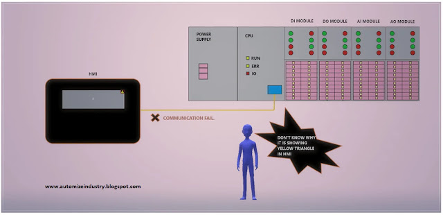
Once the IO’s have been tested, you
now to check the communication protocols used in the panel. For example, if you
have used a PLC along with HMI on Modbus TCPIP, check the communication between
them. Accordingly, if there are other protocols of communication used for field
devices in the panel, then check them too properly.
After this, you can verify that the
panel has been tested properly.
Reference
articles for more understanding written by me:
·
Factory Acceptance Test of a PLC panel:
·
Site Acceptance Test:
·
How to check the digital inputs and outputs of a PLC:
· How to check the analog inputs and outputs of a PLC:
I have covered the general example of panel testing. I have
also not attempted to cover every theory of these testing deeply; you can learn
it easily once you get familiar with them. I have just given you an insight of
these types of controls. Once you are done with these, I am hopeful you will be
easily able to understand any testing properly. Learn the basics and explore a
new type of study in this type of automation. It will take some practice and as
you go on testing the panels, you will become more familiar with it.
Thank you guys; I hope you enjoyed reading the
practices normally used for this type of study in industrial automation.

Comments
Post a Comment
If you have any queries, please let me know