Troubleshooting Digital Inputs and Outputs in PLC
17 May 2020.
In this post, we will cover the basic topics on how to check PLC inputs and outputs. This post of PLC troubleshooting is divided in two parts. Our first part will cover digital inputs and digital outputs. The next part will cover analog inputs and analog outputs. (Click on the images for a more zoomed view)
PLC inputs and outputs:
A PLC has
four types of hardware inputs and outputs: digital input, digital output, analog
input, and analog output.
A PLC
digital input is the hardware input to PLC, whereas a PLC digital output is the
hardware output from PLC. Both have only two states of operation – on or off.
In the programming language, it is referred as either bit 0 or bit 1. For
example, digital IO’s for a PLC can be a switch or a motor.
A PLC analog
input is the hardware input to PLC, whereas a PLC analog output is the hardware
output from PLC. Both are variant in operation and their signals vary in a
range from a minimum vale to a maximum value. For example, analog IO’s for a
PLC can be a temperature sensor or a modulating damper.
Let’s get a deeper look on each type.
What is sinking and sourcing in PLC?
First, let us understand what sinking and sourcing in plc is. The terms “sourcing” and “sinking” refer to the direction of current (as denoted by conventional flow notation) into or out of a device’s control wire. A device sending (conventional flow) current out of its control terminal to some other device(s) is said to be sourcing current, while a device accepting (conventional flow) current into its control terminal is said to be sinking current. We will have a look of sink and source wiring in plc later in this post for better understanding.
PLC digital input:
A digital input has two types of working – sink and source. Refer the below image for more clarification.
Conventional current flows from positive potential to negative potential. In simpler terms, just remember that when the PLC common terminal is connected to 0V, then the input will be referred as sinking input as the input is getting potential from external field device. When the PLC common terminal is connected to 24V, then the input will be referred as sourcing input as the input is giving potential to the external field device.
The voltage supply potential can be DC or AC. The common standards used are 24V DC or 24V / 110V AC.
Now, let us consider the following diagram below for troubleshooting any fault in digital input. The wiring done here is of sinking type and the blue line is the internal contact circuitry of field device. It is recommended to follow the given steps for fault finding:
1. The basic step a programmer should check is to first verify the specifications of the digital input for the corresponding PLC that he is checking. It can be like, what are the voltage specifications and what the type of wiring to be done is. Maybe the voltage to given is DC potential, but the wiring done there is of AC potential. Or the second case would be that; the wiring to be done is sink one, but the wiring done is of source one. Check whether the power source (DC or AC) is supplying proper voltage or not. Keep the document/technical catalogue of sensor and PLC module ready for testing.
2. Verify whether the address used in PLC program for the digital input is correct or not.
3. Mostly, all the digital input modules of PLC manufacturers have LED displays on it, for status display of individual channels. So, it would be easier for you to check the status. But guys, LED’s too can sometimes become faulty. So, voltage checking is the most reliable step for verifying the health of the input. Let us consider two different scenarios for troubleshooting. In the first scenario, 24V supply is coming across input-2 and common terminals properly; and you are not able to read that input in program. If the address used in the logic is correct and the voltage is coming properly, then the internal PLC circuitry of input-2 has become faulty. So, shift the wiring of input-2 to input-1 and check the status then.
4. In the second scenario, 24V supply is not coming across input-2 and common terminals properly. Trace the wiring that has been done according to our image reference shown and verify that there is no wire-break in between. If the wiring is perfectly right, then just connect the 24V wire directly to input-2 terminal. If the input is still not being read properly now, then the input is faulty. If the input is being read properly now, then the input is healthy to operate and there is some problem in field device operation or terminal board.
Now, to find the real culprit; first remove the field wiring and
loop/short the terminals on terminal board directly with a wire as shown in
given figure:
If the input is now being read properly, then there is a problem in field device operation. If it is still not being read properly, then shift the terminal board wiring to spare terminals and repeat the step.
PLC digital output:
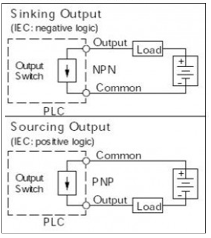
A digital output has two types of working – sink and source. Refer the below image for more clarification.
Conventional current flows from positive potential to negative potential. In simpler terms, just remember that when the PLC common terminal is connected to 0V, then the output will be referred as sinking output as the output is getting potential from external field device or load as in the image. When the PLC common terminal is connected to 24V, then the output will be referred as sourcing output as the output is giving potential to the external field device.
In terms of potential, there are two types of digital outputs - relay and solid-state. Relay outputs are mechanical contacts which work in either of the potentials, and solid-state outputs make take the form of transistor or TTL logic (DC) or Triac (AC). The type of the output unit selected will depend upon the outputs being controlled and the power available for controlling these devices. Typically, power for driving output devices must be separately provided since there can be a wide range of requirements depending upon the device.
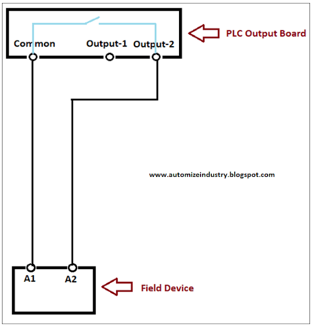
Now, let us consider the following diagram below for troubleshooting any fault in digital output or a question that every programmer asks - plc output not working. The wiring done here is of sinking type and the blue line is the internal contact circuitry of PLC output. It is recommended to follow the given steps for fault finding:
1. The basic step a programmer should check is to first verify the specifications of the digital output for the corresponding PLC that he is checking. It can be like, what are the voltage specifications and what the type of wiring to be done is. Maybe the voltage to given is DC potential, but the wiring done there is of AC potential (Relay output can work in any given potential; this test applies only for triac or transistor outputs). Or the second case would be that; the wiring to be done is sink one, but the wiring done is of source one. Check whether the power source (DC or AC) is supplying proper voltage or not. Keep the document/technical catalogue of sensor and PLC module ready for testing.
2. Verify whether the address used in PLC program for the digital output is correct or not; and whether the output is on or not through logic.
3. If the output is on, remove the wiring from PLC terminals and connect a multi-meter across common and output-2 terminals. Check it’s continuity. If it shows connectivity (indicated by a beep sound), then the internal contact of PLC output is working properly; and if not, then the output is faulty.
4. Mostly, all the digital output modules of PLC manufacturers have LED displays on it, for status display of individual channels. So, it would be easier for you to check the status. But guys, LED’s too can sometimes become faulty. So, voltage checking is the most reliable step for verifying the health of the output.
5. Let us move ahead further for troubleshooting. If you have found that the PLC output is intact, reconnect the wiring across PLC terminals and trace the wiring that has been done according to our image reference shown. Verify that there is no wire-break in between.
6. Let us consider two different scenarios for troubleshooting. In the first scenario, if the wiring is perfectly right and 24V supply is not coming across A1 and A2 terminals of relay board properly; then the PLC output is faulty. In the second scenario, if 24V supply is coming across the terminals, then move ahead for NO and common terminals of relay board. As the relay has now been energized, the contacts should work.
7. Remove the wiring across these terminals and check it’s continuity. If it is not showing continuity, then the contacts are not working properly. If it is showing continuity, then reconnect the wiring and check the voltage across A1 and A2 terminals of field device. If the voltage is coming properly and still the device is not operating, then the issue is concluded in field device. If the voltage is still not coming across the terminals, then the NO and common terminals of relay board are not working properly and needs to be replaced.
There are many control devices where
only a contact switching is required from PLC to operate the device. The device
is powered internally from another source. In that case, only continuity check
is required, and proper wire tracing needs to be done to troubleshoot any
issue. You can refer the above topic that was discussed for digital outputs.
Refer the image below that I am trying to convey. Remember guys, PLC output is
just a contact and doesn’t compulsorily require a potential voltage for
operation. It concludes that the instrument which requires voltage control from
PLC will require a relay board in between for safety purpose; and the
instrument which requires only a switch type control from PLC can also be
operated as discussed.
This lesson has been a basic introduction to the most common sorts of digital inputs and outputs used in PLC-based applications. Each of the types covered here has its quirks, and the ways the PLC digital I/O’s are built differ between manufacturers and PLC models, so I have just covered general principles without enough detail to implement them in any given PLC system. I have also not attempted to cover every type of device. Each manufacturer has unique ways of handling measurements, and there are many other sorts of instruments that we have not included here.
Thank you,
guys; we will cover the troubleshooting for analog inputs and analog outputs in
second part. If you have any views or know some more methods, then I would
be happy to get a comment from you.


Comments
Post a Comment
If you have any queries, please let me know