Troubleshooting Analog Inputs and Outputs in PLC
17 May, 2020.
In this post, we will cover the basic topics on how to troubleshoot faults in hardware inputs and outputs of a PLC. Our first part covered digital inputs and digital outputs. This part will cover analog inputs and analog outputs.
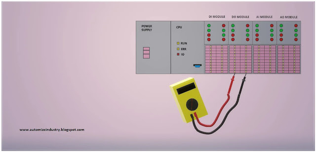
Types of Hardware PLC inputs and outputs:
Hello Guys. Welcome back to our study. I hope you enjoyed reading the first part on how to troubleshoot digital PLC I/O’s.
Let’s get a look now on how to find faults in PLC analog inputs and PLC analog outputs.
Analog Inputs:
Basically, three types of analog signals are used in PLC programming – voltage, current and resistance. To further diversify it, the most common types of analog inputs used in PLC accordingly are:
· 0-10 V
· 4-20 / 0-20 mA
· RTD
· Thermocouple
The raw signal coming from these sources are converted into counts through Analog-to-Digital Converter inside the PLC circuitry. The system inside works in binary numbers. A binary number with one digit is called a bit. One bit can hold either a 0 or a 1. As mentioned, this is how digital inputs work. But if you combine these bits and thereby create multiple digit numbers, things start to get interesting. In many PLC’s an analog signal is represented by a word. A word in binary is 8 zeros’ in a row or two bytes (4 zero’s). Just like this:
00000000 00000000
If you remember a little bit about binary numbers you will know, that a binary number with 16 digits can represent values from 0 to 65535. This is only half the truth for PLC’s though. Because the first bit is used for signing the number, giving it either a positive or negative value. So with 1 bit for signing we have 15 bits left for representing the analog value. The binary number can therefore represent values from -32768 to 32767. Consider the below graph for a 0-10 V analog signal which is scaled in the range of 0-10000 counts in PLC.
Every PLC has it’s own set of scaling parameters inside the program; which are either fixed or settable. Nowadays, most PLC’s only give the facility for user-settable counts inside the program configuration for analog inputs. This has diversified and simplified the work of a programmer to a very large extent.
Analog signals tend to be very sensitive. Although it is our intention that a signal range should be from 4-20mA, the signal can sometimes peak or drop. When that happens, we want to be able to see that in the PLC. Although it is not always the case these peaks and drops can mean that there is something wrong. To be able to detect these in out PLC program, we need what is called over- and under range. Our normal range or rated range is 0-10V. But on top and below that; Schneider, for example in M340 PLC, had added some extra V in the range. They divide the over range in these two categories: below (-800) and above (10800).
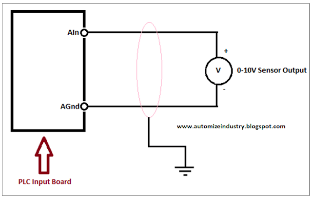
Now, let us consider the following diagram below for troubleshooting any fault in analog input. It is recommended to have some other source of testing, like a source-meter, for troubleshooting. It is not feasible for a programmer or another user to have it every time; but it is considered for worst scenario. Consider the first case of voltage wiring (0-10V). When you’re connecting the analog voltage source, the AIN is where you connect the positive (+) side of it. The negative side (-) should be connected to AGND. Those are the two main wires for the analog signal. But if you only connect those two, you will end up with a very vulnerable signal. Electromagnetic compatibility (EMC) can easily alter your analog signal. As you can see below, this is solved by shielding the wires and connecting the shield to ground. Be aware though that this is NOT the same ground as the AGND!
It is recommended to follow the given steps for fault-finding:
· The basic step a programmer should check is to first verify the specifications of the analog input for the corresponding PLC that he is checking. It can be like, what are the specifications/types of analog input that the module is accepting and what the type of wiring to be done is. Maybe the sensor to connect is voltage type, but the sensor connected is of current type. Keep the document/technical catalogue of sensor and PLC module ready for testing.
· Verify whether the address used in PLC program for the analog input is correct or not. Verify whether the channel is configured properly in program.
· Mostly, all the analog input modules of PLC manufacturers have LED displays on it; for status display of individual channels. So, it would be easier for you to check the status. It will show whether the channel is connected to any input or not; or whether the channel is faulty or not.
· Check the voltage across the sensor terminals first. Suppose it is a temperature sensor. It gives an output of 0-10 V for a temperature range of 0-50 deg C. If it is not showing voltage across it, then the sensor needs to be replaced. If it is showing voltage, then reconnect the wires across PLC and check the voltage across PLC terminals. If it is showing voltage and then too the raw counts are not reflecting in PLC program, then the PLC channel is faulty.
· Since we’re dealing with voltage here, there is something about the wiring itself that can cause problems. All electrical wires (conductors) have resistance and hence creating a voltage drop. This could potentially mean that the voltage at the analog input is different than the voltage at the transmitter. This of course only has a significant consequence if you have long distances of wiring or too small wires.
Consider the second case of current wiring (0-20mA / 4-20mA). You need a closed loop for current to flow; as current is the flow of electrons from one pole to another. Keeping this thing in mind, there are 3 types of wiring mostly done in current sensing – 2-wire, 3-wire and 4-wire. When talking about 2, 3 and 4 wires, what we’re talking about here is really the transmitters or transducers. Current transmitters can be wired in different ways and therefore with a different number of wires. The difference is really the power supply for the signal. Sometimes the transmitter will supply the circuit, and sometimes you have to use an external supply.
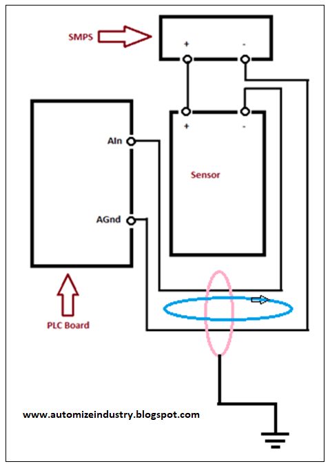
The first and a simpler one is a 2-wire sensor; which is loop-powered. It implies that there are only two wires in the sensor for connection. See the below wiring for reference:
The positive end of power supply (SMPS) goes to positive pin of sensor. The negative pin of sensor goes to positive pin of PLC. The negative pin of PLC is connected to negative point of SMPS. This completes the loop. The flow starts from positive point of SMPS and ends at negative point of SMPS. The pink line shows the shielding done and the blue line shows the current flow.
It is recommended to follow the given steps for fault-finding:
· The basic step a programmer should check is to first verify the specifications of the analog input for the corresponding PLC that he is checking. It can be like, what are the specifications/types of analog input that the module is accepting and what the type of wiring to be done is. Maybe the sensor to connect is current type, but the sensor connected is of voltage type. Keep the document/technical catalogue of sensor and PLC module ready for testing.
· Verify whether the address used in PLC program for the analog input is correct or not. Verify whether the channel is configured properly in program.
· Mostly, all the analog input modules of PLC manufacturers have LED displays on it; for status display of individual channels. So, it would be easier for you to check the status. It will show whether the channel is connected to any input or not; or whether the channel is faulty or not.
· Check the voltage across the power supply first. Then, suppose it is a temperature sensor. It gives an output of 0-20 mA for a temperature range of 0-50 deg C. Any loopholes in wiring; and current won’t show at PLC positive terminal. Check the voltage across sensor positive pin and SMPS negative pin. Check the current across negative pin of sensor and positive pin of PLC; in series. If it is showing current and then too the raw counts are not reflecting in PLC program, then the PLC channel is faulty. If it is not showing current across it, then the sensor needs to be replaced.
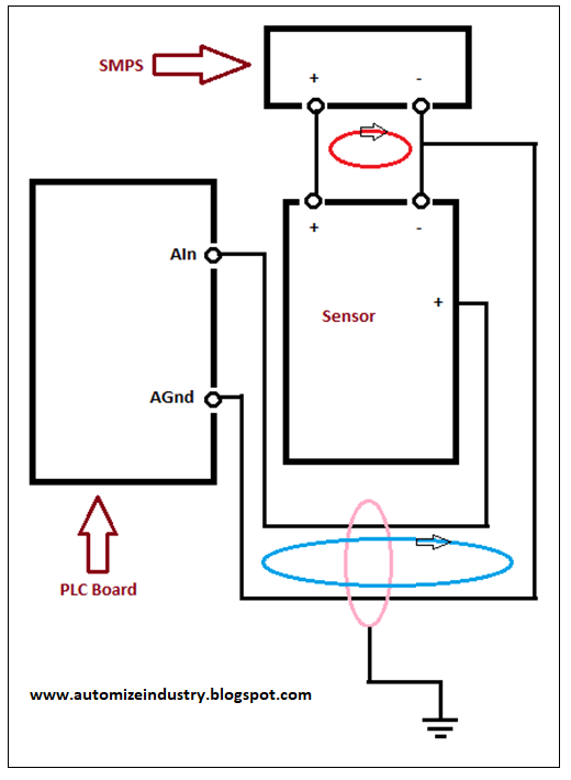
The second one is a 3-wire sensor. It implies that there are only three wires in the sensor for connection. In a 3 wire current loop, only the ground is shared between the supply and the signal. See the below wiring for reference:
The positive end of power supply (SMPS) goes to positive pin of sensor. The negative pin of power supply goes to the negative pins of PLC and sensor. The positive pin of sensor is connected to positive point of PLC. The pink line shows the shielding done, the blue line shows the current flow and the red line shows the power flow.
The steps in troubleshooting are same as discussed earlier in 2-wire sensor; except for the last point, which is mentioned as below:
· Check the voltage across the power supply first. Then, suppose it is a temperature sensor. It gives an output of 0-20 mA for a temperature range of 0-50 deg C. Any loopholes in wiring; and current won’t show at PLC positive terminal. Check the voltage across sensor pins. Check the current across positive pin of sensor and positive pin of PLC; in series. If it is showing current and then too the raw counts are not reflecting in PLC program, then the PLC channel is faulty. If it is not showing current across it, then the sensor needs to be replaced.
The third one is a 4-wire sensor. It implies that there are only four wires in the sensor for connection. In a 4 wire current loop, the supply and signal is separated. See the below wiring for reference:
The positive end of power supply (SMPS) goes to positive pin of sensor. The negative pin of power supply goes to the negative pins of sensor. The positive pin of sensor is connected to positive point of PLC and the negative pin of sensor is connected to negative pin of PLC. The pink line shows the shielding done, the blue line shows the current flow and the red line shows the power flow.
It’s troubleshooting is same as a 3-wire sensor.
Now, consider the third case of temperature wiring (thermocouple). This type of device generates a small signal, in the milli-volt range, depending on the temperature at the “junction” the point where two different metals touch to create the voltage. A thermocouple is made up of at least two different conductors (metals) that are joined together in such a manner that they form two distinct junctions. For example, if you take two iron wires and one copper wire, and twist one end each of both the iron wires to either ends of the copper wire; you would effectively get a thermocouple, with two separate iron-copper junctions. One of these junctions is known as the hot junction, and will be connected to the body whose temperature needs to be measured. The other junction is called the cold junction, and is either kept open or is connected to another body whose temperature is known and used as a reference. When the hot junction is heated, the difference in temperature between it and the cold junction is converted to proportional voltage which is measurable. This forms the basic working principle of a thermocouple. The voltage thus generated is further used to control different voltage-driven circuits in various applications. The temperature range of a thermocouple is specified by a single letter, I.e., a “Type J” thermocouple is a common variety with well-known characteristics.
See the below wiring for reference:
It is recommended to follow below steps for troubleshooting:
· The basic step a programmer should check is to first verify the specifications of the analog input for the corresponding PLC that he is checking. It can be like, what are the specifications/types of analog input that the module is accepting and what the type of wiring to be done is. Keep the document/technical catalogue of sensor and PLC module ready for testing.
· Verify whether the address used in PLC program for the analog input is correct or not. Verify whether the channel is configured properly in program.
· Mostly, all the analog input modules of PLC manufacturers have LED displays on it; for status display of individual channels. So, it would be easier for you to check the status. It will show whether the channel is connected to any input or not; or whether the channel is faulty or not.
· Suppose we are testing a thermocouple attached in a gas appliance. There are three procedures used commonly for testing a thermocouple. The first one is the resistance test. Connect the crocodile clips to the slots in the multimeter. Now, attach one clip on one end of the thermocouple and attach the other clip on the other end, which is the one that gets screwed into the gas valve. Turn on the multimeter and select the ohms/resistance reading option. The multimeter should display a very small resistance in the order of a few ohms, if the thermocouple is fine. Otherwise, put the multimeter on the continuity option. If your thermocouple is good, then you will hear a continuous audio tone. A high resistance, for example 40 ohms is indicative of a bad thermocouple which must be replaced.
· The second one is the open circuit test. Place one of the test leads of the multimeter on the side of the thermocouple and the other to the end that enters the gas valve. Ignite a lighter or other heat source with a flame, at the opposite end of the thermocouple. Thermocouples designed for residential gas appliances, such as fireplaces, water heaters and furnaces, are made for 30 millivolts. The reading should be between 25 and 30. Anything under or hovering around the 20 millivolts mark means the thermocouple needs to be replaced. Discretion should be used if the reading is between 21 and 25.
· The third one is the close circuit test. Perform a closed circuit test using the thermocouple adapter to achieve true performance ability under load. Many manufacturers provide these adapters for testing purposes, and they are also easily available in stores. This adapter is screwed inside the gas valve. The thermocouple is then screwed into the other end of the adapter. It is easier to perform this test using crocodile clips attached to the test leads. First, attach the thermocouple adapter to the gas valve in the thermocouple's spot. Then attach the thermocouple as normal with the exception that the end that would screw into the gas valve will screw into the adapter. Select the millivolt reading option in the multimeter, and turn on the appliance. Ideally, the reading should range between 12 mV to 15 mV. If the thermocouple outputs voltage below 12 mV, there is a significant drop, meaning that it is defective and needs to be replaced.
· In these three procedures, if you are getting a satisfactory result from sensor but the raw counts are still not showing in the program; then it is recommended to change the PLC channel in the program.
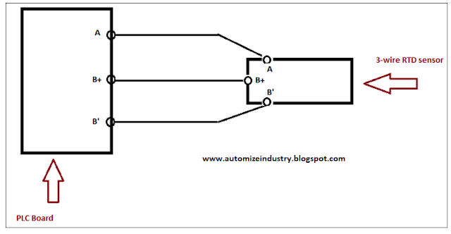
Now, consider the fourth case of RTD or Resistance temperature detectors. As the name implies, this transducer directly converts temperature into resistance. It is relatively an easier instrument for testing, as compared to a thermocouple. This sensor comes mostly in 3-wire or 4-wire configuration.
See the below wiring for reference. The PLC module shown here is of Schneider-make (TM3TI4):
It is recommended to follow below steps for troubleshooting:
· The basic step a programmer should check is to first verify the specifications of the analog input for the corresponding PLC that he is checking. It can be like, what are the specifications/types of analog input that the module is accepting and what the type of wiring to be done is. Keep the document/technical catalogue of sensor and PLC module ready for testing.
· Verify whether the address used in PLC program for the analog input is correct or not. Verify whether the channel is configured properly in program.
· Mostly, all the analog input modules of PLC manufacturers have LED displays on it; for status display of individual channels. So, it would be easier for you to check the status. It will show whether the channel is connected to any input or not; or whether the channel is faulty or not.
· Set your multimeter in resistance mode. Check the readings across the terminals of the RTD. At room temperature the reading should be around 110 ohms. The reading may vary depending on the metal in the RTD. Place the RTD in ice water. Give it a couple minutes to adjust and check the readings. You should get a lower number than the room temperature reading, around 100 ohms. Give the RTD time to adjust to room temperature after removing it from the ice water. Place the RTD in boiling water and check the readings again. The number should be higher than the room temperature reading if your RTD is functioning properly. In this procedure, if you are getting a satisfactory result from sensor but the raw counts are still not showing in the program; then it is recommended to change the PLC channel in the program.
Analog Outputs:
Basically, two types of analog signals are used in PLC programming – voltage and current. To further diversify it, the most common types of analog inputs used in PLC accordingly are:
· 0-10 V DC.
· 4-20 / 0-20 mA
It’s theory is exact opposite of analog input; that we discussed earlier. It converts the software signal into hardware signal.
Now, let us consider the following diagram below for troubleshooting any fault in analog output. Consider the first case of voltage wiring (0-10V). Here, we have taken a 2-wire load connection. When you’re connecting the analog voltage output, the AIN is where you connect the positive (+) side of it. The negative side (-) should be connected to AGND. Those are the two main wires for the analog signal. But if you only connect those two, you will end up with a very vulnerable signal. Electromagnetic compatibility (EMC) can easily alter your analog signal. As you can see below, this is solved by shielding the wires and connecting the shield to ground. Be aware though that this is NOT the same ground as the AGND!
It is recommended to follow the given steps for fault-finding:
· The basic step a programmer should check is to first verify the specifications of the analog output for the corresponding PLC that he is checking. It can be like, what are the specifications/types of analog output that the module is giving and what the type of wiring to be done is. Maybe the load to connect is voltage type, but the load connected is of current type. Keep the document/technical catalogue of load and PLC module ready for testing.
· Verify whether the address used in PLC program for the analog output is correct or not. Verify whether the channel is configured properly in program.
· Mostly, all the analog output modules of PLC manufacturers have LED displays on it; for status display of individual channels. So, it would be easier for you to check the status. It will show whether the channel is connected to any output or not; or whether the channel is faulty or not.
· Remove the wires from PLC terminals. Check the voltage across the PLC terminals first. Suppose the load is a modulating damper. It accepts an output of 0-10 V for operating it’s position in the range of 0-100%. If it is not showing voltage across it after the counts have been given from program, then the PLC output needs to be replaced in the program. If it is showing voltage, then reconnect the wires across PLC and check the voltage across load terminals. If it is showing voltage and then too the damper is not responding, then the damper is faulty.
There are even 3-wire load connections. Take the below image for reference. Here, the U terminal of load is connected to AOut terminal of PLC. AGnd pin of PLC and negative pin of the load are connected to negative terminal of power supply. Positive pin of the load is connected to positive pin of the power supply. This completes the circuit. The steps for troubleshooting are the same, except for below point:
· Remove the wires from PLC terminals. Check the voltage across the PLC terminals first. Suppose the load is a modulating damper. It accepts an output of 0-10 V for operating it’s position in the range of 0-100%. If it is not showing voltage across it after the counts have been given from program, then the PLC output needs to be replaced in the program. If it is showing voltage, then reconnect the wires across PLC and check the power supply across the load. After confirmation, check the voltage across U terminal and negative pin terminal of the load. If it is showing voltage and then too the damper is not responding, then the damper is faulty.
Guys, standard voltage output from PLC is in DC potential. But, if you have a load which requires 0-10V AC for a power supply source of 24V AC; then don’t worry. You just have to connect negative potential of power supply to the negative pin of PLC output. The load will start to operate.
Analog current output troubleshooting is the same as analog voltage theory that we discussed.
One big difference between the current and voltage outputs is the load impedance. Because where voltage outputs would require a minimum load impedance, the current outputs actually has maximum load impedance. Remember, we’re talking flow of current here and impedance (resistance) limits the current. If the load impedance is too big, the loop will simply not be able to drive the current flow needed. A typical PLC analog current output has a maximum load impedance of 300-500 Ohm.
This lesson has been a basic introduction to the most common sorts of analog inputs and outputs used in PLC-based applications. Each of the types covered here has its quirks, and the ways the PLC analog I/O’s are built differ between manufacturers and PLC models, so I have just covered general principles without enough detail to implement them in any given PLC system. I have also not attempted to cover every type of device. Each manufacturer has unique ways of handling measurements, and there are many other sorts of instruments that we have not included here.
Thank you guys; I hope you enjoyed reading the practices normally used for this type of troubleshooting in industrial automation. If you have any views or know some more methods, then I would be happy to get a comment from you.






Goodness, What an Excellent post. I truly discovered this to much educational. It is the thing that I was looking for multimeter.
ReplyDelete