Convert Ladder Logic into Structured Text and Functional Block Diagram
12 July 2020.
In this
post, we will cover the basic topics on how to convert ladder language logic
into structured text and functional block diagram languages. We will use Unity
Pro software for study. (Click on the images for
a more zoomed view)
Hello programmers. Ladder logic is a
very commonly used programming language in industrial automation. In fact, when
programmers venture into the world of automation for first time, they are
mostly trained in this language as it is simplified and resembles traditional
electrical drawing circuits to a very great extent. Over the time, I learnt
that though this language is easy to write; it has great drawback of length and
online view, which irritates a lot sometimes. Means; if you have written a
ladder section comprising around 100 rungs, imagine how much you will have to
scroll down and up to view and troubleshoot. Moreover, when many rungs are
written in a section, the software takes some amount of time to load the
animation when online. This can prove to be a waste if you are in urgent need
of finding the bug which comes and moves away instantly, and the software is
not able to help you. So, we must adapt to other programming languages for
quick troubleshooting and improving the efficiency and view of the program. You
can use ladder logic in the program but try to use it only somewhere and not
the whole program.
I have come across many freshers who
avoid using other languages. They either don’t know how to write their ladder
logic in some other language same to same or they are least interested in
transforming to some other code and just stick to their basic language. So, I
will teach you on how to convert your ladder logic into other language logic
and improve your programming standards. Guys, we will cover structured text and
functional block diagram languages. These are widely used and overall enhance
the view, efficiency and working of the program.
How to convert Ladder Logic to Functional Block Diagram and Structured Text:
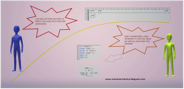
Let’s start by referring the ladder
logic below. I will consider that the readers are efficient in working in
ladder logic; because our focus is to convert and write them in other
languages. As you can see, lamp variable turns on when start variable
turns on and stop variable is off. This will latch the lamp variable
below start variable and will maintain the power of the rung
to keep lamp variable on.
Structured Text Programming In PLC:
So, let’s start with structured text language. Structured Text is PLC programming language defined by PLCOpen in IEC 61131-3. The programming language is text-based, compared to the graphics-based ladder diagram or Function Block Diagram. The syntax of this language is made like high-level programming languages like PHP, Python, and C etc., with loops, variables, conditions, and operators. It is important to understand the structure and syntax of the structured text before you proceed ahead. You can then easily understand how the flow of the program works. As you can see in the image below, it runs till the end statement of the program and will continue from start again. It is like ladder language. There are many types of statements used in this language – if-else, case, while, repeat, for etc. We will see if-else statement here.
Read and understand the syntax properly. It is full of colons, semicolons, and other symbols. Each of them has it’s meaning. Semicolon separates a statement and indicates that the end of a statement has been reached. If you are comparing something, then use = symbol; and if you are writing something into a variable, then use: = symbol.
We will now convert ladder to
structured text. Let’s start with the logic now. If you remember the ladder
logic that we had seen, lamp variable is latched once start variable
turns on. It unlatches only when stop variable turns on and
cuts the power of the rung. Now, read and understand how I wrote this in
structured text. If start variable turns on, then we are
writing value 1 to lamp variable. Now, when start variable
turns off, then too lamp variable will remain on; because the
condition to execute the statement is false. This means the lamp variable has
been latched now. If stop variable turns on, then we are
writing value 0 to lamp variable. Now, when stop variable
turns off, then too lamp variable will remain off; because the
condition to execute the statement is false. Then, as there are two if statements;
we have terminated them with two end statements. I am thus
conveying, that what you wrote in ladder logic; interpret each rung in your
mind and make the statements. It’s simple; analyze each element in the ladder
rung, understand it’s role and write that same in structured text. One you
understand how the final output variable is impacted, then you can easily write
the statement.
You can also write this statement as
below. In the first image, I have just changed the visualization of the program
for better understanding. In the second image, I have replicated the ladder
logic in structured text format. Here, I have simply used assignment statement.
Means, the final variable lamp will be written as 1 when the
whole condition is true and written as 0 when the whole condition is false. So,
it all depends on you and how you want to visualize and understand the
statement. If you are not familiar with structured text language, you can find
many structured text programming pdf files online for understanding.
Functional Block Diagram PLC Programming:
Now, let’s start with functional block
diagram. It is a simple and graphical way to program any functions together in
a PLC program. Most programmers love FBD because it is graphically a very
common way to describe a system and they like to put things in boxes. And that
is exactly what the concept of function block diagrams is. FBD is nothing but,
functions put in function blocks. They all have one or more inputs and outputs.
The function of the block is the relation between the state of it’s inputs and
outputs.
As you can see in the below image, a function block is shown as a box. In the middle of the box is often a symbol or a text. This symbol represents the actual functionality of the function block. Depending on the function there can be any number of inputs and outputs on the function block. You can connect the output of one function block to the input of another. Thus, a Function Block Diagram is created. FBD looks great in visualization as the whole logic appears in front of your eyes at one go; and helps you in better troubleshooting.
We will
now convert ladder to function block diagram. Let’s start with the logic now.
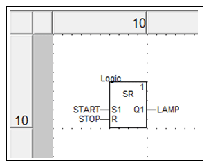
As in the image, SR represents SR flip
flop logic. When a variable turns on at S1 input (S1 means set), the output Q1 is latched. It will remain latched until the
variable at R input (R means
reset) turns on and will unlatch the output. So, as per our previous study, I
just latched the lamp variable
with a start variable at S1
input and unlatched it with a stop variable
at R input.
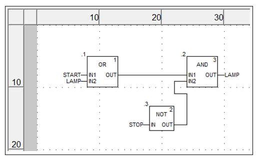
You can also write the logic as
follows. I have replicated the ladder logic into functional block diagram. I
would suggest for first timers; use this logic for understanding. Understand
the ladder logic first and convert it as same into functional block diagram.
Learn how to link blocks first; because once you can link the blocks and write
the logic properly, then it would be easier for you to go for standard and
advanced level blocks in the software. Remember guys; always start from
scratch.
Some important points to remember are:
1. Ladder and functional block
programming differ in terms of representation with one using ladder diagram and
the other using functional block variables and boxes.
2. Ladder and structured text
programming differ in terms of representation with one using ladder diagram and
the other using syntax, and statements.
3. If it is difficult for you as to how to write a logic in programming, first understand the logic and draw it in your own language through flowcharts or free-hand drawings. It helps a lot.
I have covered the general principles which normally are followed to write logic in structured text and functional block diagram. I have also not attempted to cover every type of statements and blocks; you can learn it easily in the software help file or internet. I have just taught you on how to convert and write your ladder logic into some other language. Learn the basics, save time in your coding, make it appear better and improve the efficiency and productivity of your work.
Thank you, guys; I hope you enjoyed reading the practices normally used for this type of study in industrial automation.


This site have particular software articles which emits an impression of being a significant and significant for you individual, able software installation.This is the spot you can get helps for any software installation, usage and cracked.
ReplyDeleteunity-pro-crack-free-download
serato-dj-pro-crack-license-key
bandicam-crack-keygen
spynote-cracked-tutorial-latest
Goood Working...Thanks for shairng keep it up!
ReplyDeleteModbus Poll 9.9.0 Crack
Heyy viral ...this article helped .. keep posting ..!!
ReplyDeletePrompt n precise content ...worth it .!!
ReplyDeleteVirla...Great post..It helps..Keep posting
ReplyDeleteThis is a good blog it is very useful for me if you need this P.Eng. Certification if you want to become a P.Eng then visit our website
ReplyDeleteThis is an awesome post. Really very informative and creative content. This concept is a good way to enhance knowledge.Thank you for this brief explanation System changes and upgrades for commercial electrical systems in New Westminster
ReplyDelete