Ladder Logic Symbols
19 March, 2023.
In this post, we
will see the concept of ladder logic symbols.
PLC programming consists of five languages – ladder logic, structured text, functional block diagram, instruction list and sequential flow chart. This is according to IEC 61131-3 syntax. One of the easiest languages to learn for a new programmer is the ladder logic. Ladder logic is very flexible to learn, because we can easily co-relate it with the standard control wiring diagrams that were used earlier before invention of PLC’s. Whenever some new person enters PLC programming field, he is taught ladder logic initially. So, it is necessary to understand it’s basics clearly; because then we can work easily with higher level languages. For that, it is required to get through the symbols used in it. If we are able to interpret the symbols used in it, then we can easily develop the logic in it. In this post, we will see the concept of symbols used in ladder logic.
·
What is
ladder logic?
Ladder logic, as discussed earlier, is a type of PLC programming language. As the name implies, it can be viewed as a ladder of elements placed from top to bottom. It is a series of rungs present, where you can use the symbols in it as required. The ladder logic can be co-related with a standard control wiring diagram. In wiring, there is a power source (positive end), which is followed by the placing of contacts and coils; and is then terminated by a power source (negative end). The same logic is used here too. There is a rung in it. The rung has two power rails in both the ends. The elements are connected between both the rails in a single rung. When the power flows from one rail to other rail successfully (means the logic becomes true to turn on a coil), then that means the rung is on now. If the coil goes off, then that means the rung is off now. Multiple such rungs are written in a program. The program is then executed from top rung to bottom rung.
· Ladder diagram symbols:
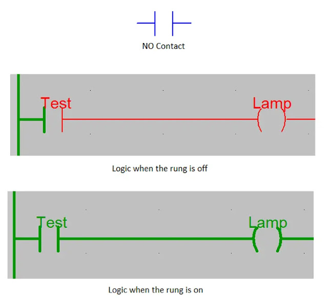
1. 1. NO
Contact:
NO contact stands for normally open. Normally open means that when the contact is not triggered, it will remain in off condition by default. When the contact is triggered, it goes in on condition. This means that the variable linked with an NO contact will turn it on when it is itself in on condition. Refer the below image. As shown, a variable named Test is used in the NO contact. When the variable is off, then the rail is not powered and the coil named Lamp will remain off. When the variable is on, then the rail is powered and the Lamp variable will turn on.
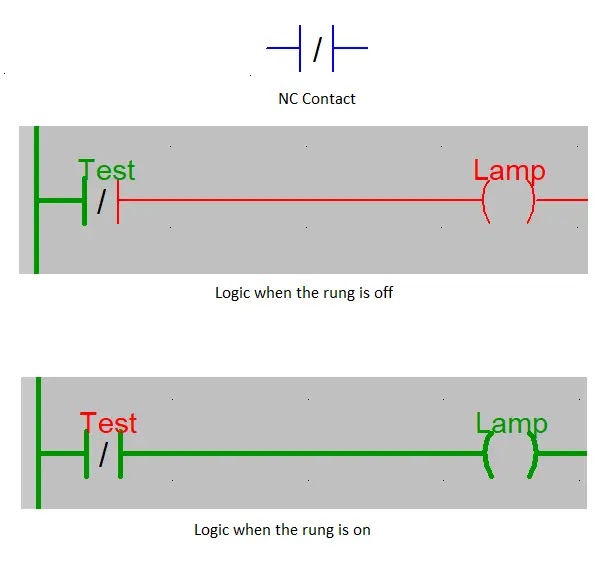
. 2. NC Contact:
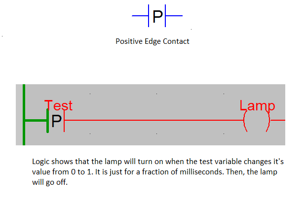
3. Positive Transition Sensing Contact:
Positive Transition sensing contact means that when
the contact is triggered, it will just give a trigger to the coil. Comparing it
to the previous types where the contact was continuously required to be on,
this type of contact only gives a pulse-type shot to the coil when the variable
linked with it changes from 0 to 1. Refer the below image for understanding. As
shown, a variable named Test is used
in the positive pulse contact. When the variable is on, then the rail is
powered for some microseconds and immediately goes off. During this small
interval time, the coil named Lamp will
remain on. The lamp variable will not remain continuously on. It was triggered
only for a time which is even not visible to the human eye.
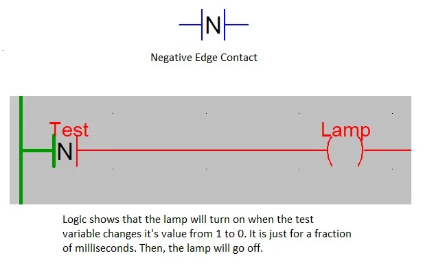
4. Negative Transition Sensing Contact:
Negative Transition sensing contact means that when
the contact is turned off, it will just give a trigger to the coil. Comparing
it to the previous types where the contact was continuously required to be on,
this type of contact only gives a pulse-type shot to the coil when the variable
linked with it changes from 1 to 0. Refer the below image for understanding. As
shown, a variable named Test is used
in the negative pulse contact. When the variable goes off from on state, then
the rail is powered for some microseconds and immediately goes off. During this
small interval time, the coil named Lamp
will remain on. The lamp variable will not remain continuously on. It was
triggered only for a time which is even not visible to the human eye.
5. Normal Coil:
Now, let us come to the coil section. Earlier we studied was the contact section. A normal coil means that when the rung is powered on, then the coil variable will turn on. When the rung goes off due to logic going off, then the coil variable will turn off. This shows that the output remains on as long as the input is on. Refer the below image. As shown, a variable named Test is used in the input logic. When the variable is off, then the rail is not powered and the coil named Lamp (the coil variable) will remain off. When the variable is on, then the rail is powered and the Lamp variable will turn on.
6. Negated Coil:
A negated coil means that when the rung is powered
off, then the coil variable will turn on. When the rung goes on due to logic
going on, then the coil variable will turn off. This shows that the output
remains on as long as the input is off. Refer the below image. As shown, a
variable named Test is used in the
input logic. When the variable is off, then the rail is not powered and the
coil named Lamp (the coil variable)
will remain on. When the variable is on, then the rail is powered and the Lamp variable will turn off.
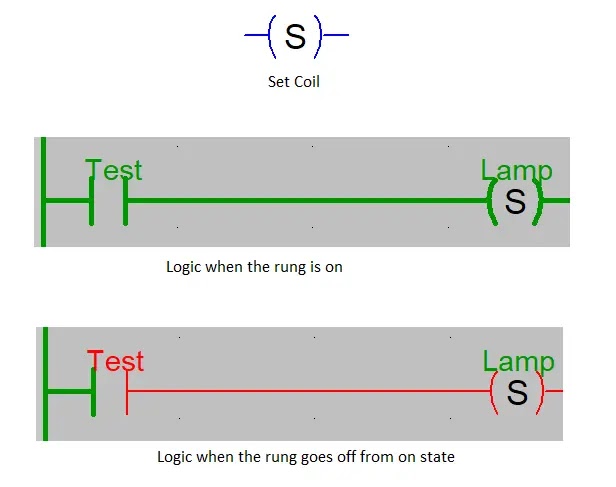
7. Set Coil:
A set coil means that when the rung is powered on,
then the coil variable will turn on. When the rung is powered off, then too the
coil variable will remain on. This means that the output remains on once it
receives the input. Then even if the input goes off, then too the output will
remain on. Refer the below image. As shown, a variable named Test is used in the input logic. When
the variable is off, then the rail is not powered and the coil named Lamp (the coil variable) will remain off.
When the variable is on, then the rail is powered and the Lamp variable will turn on. When the variable is off again, then
the rail is not powered, but the Lamp
variable will remain on.
8. Reset Coil:
A reset coil means that when the rung is powered on,
then the coil variable will turn off. When the rung is powered off, then too
the coil variable will remain off. This means that the output goes off once it
receives the input. Then even if the input goes off, then too the output will
remain off. Refer the below image. As shown, a variable named Test is used in the input logic. Let us
assume that the coil variable named Lamp
was on initially. When the input variable is on, then the rail is powered and
the Lamp variable will turn off.
When the variable is off again, then the rail is not powered, but the Lamp variable will remain off.
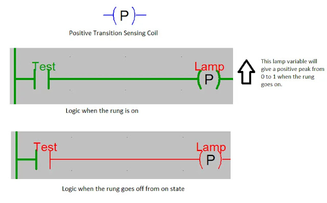
9. Positive Transition Sensing Coil:
A positive transition sensing coil means that when the
rung is powered on, then the coil variable will turn on for a fraction of
microseconds and then go off immediately. When the rung is powered off, then
too the coil variable will remain off. This means that the output gives a
positive peak type pulse once it receives the input. Then even if the input
goes off, then too the output will remain off. Refer the below image. As shown,
a variable named Test is used in the
input logic. When this input goes from off to on state, then the coil variable Lamp will change it’s state from 0 to 1
for a fraction of microseconds (invisible to human eye). It means it is giving
a positive type pulse. When the input goes off, then too the Lamp will remain off.
10. Negative Transition Sensing Coil:
A negative transition sensing coil means that when the
rung is powered off from on state, then the coil variable will turn on for a
fraction of microseconds and then go off immediately. When the rung is powered
on, then too the coil variable will remain off. This means that the output gives
a positive peak type pulse once the input goes off. Then even if the input goes
on, then too the output will remain off. Refer the below image. As shown, a
variable named Test is used in the
input logic. When this input goes from on to off state, then the coil variable Lamp will change it’s state from 0 to 1
for a fraction of microseconds (invisible to human eye). It means it is giving
a positive type pulse. When the input goes on, then too the Lamp will remain off.
I have covered the general principle of ladder logic symbols.
I have also not attempted to cover every theory of these
design deeply; you can learn it easily once you get familiar with them. I have
just given you an insight of these types of controls. A great software and logic
understanding is required by the engineer who is designing such system. Learn
the basics and explore a new type of study in this type of automation.
Thank you guys; I hope you enjoyed reading the practices normally used
for this type of study in industrial automation.







Comments
Post a Comment
If you have any queries, please let me know