PLC Program Design
3 Jan, 2023.
In this
post, we will see the concept of step-by-step designing a PLC program.
In industrial automation, if you are new to PLC programming, then it is necessary to understand their design steps properly. A PLC can be used for any industrial application. In that case, if you understand each process properly, then you will get to know that you can at least write the program properly. But, just writing the program is not the case. There are many things to consider if you want the logic to be executed fully in a bug-free manner. This helps to evaluate the process smoothly, efficiently and reliably. So, it is of utmost importance to design a PLC program in a step by step manner. In this post, we will see the concept of designing a PLC program step-by-step. We will use TIA Portal software for reference.
PLC Programming Basics:
Before starting the topic, let us have a quick look at some very basic
programming points:
1. Generally, a program has two tasks –
fast and normal. You can write
sections in a fast task where the scan time will be very low and quick. You can
write the remaining sections in a normal task where scan time is not a concern and
the PLC will execute it in it’s defined interval.
2. Five types of languages are used – ladder logic, structured text, functional
block diagram, sequential flow chart and instruction list.
3. You write the program in user application
memory; but apart from that, the PLC has operating system memory which performs
tasks like hot and warm restart, interrupt handling, managing memory areas,
executing the program written, updating IO values, and managing communication
protocols.
PLC Coding:
1. The very first step in designing a program is getting five basic
documents – IO list, system
architecture, automation BOM, P&ID and control philosophy. When you get
these documents, then it will be your first step in starting the development. IO
list gives you a summary of PLC IO’s in sequence, system architecture shows you
how the automation equipment will be interfaced with each other, automation BOM
gives you the list of automation equipment used, P&ID helps you relate with
the process flow and control philosophy helps in writing the logic. All these
are necessary before starting development
2. Once you got these documents, then
start the development. Open a new PLC project and first of all, configure the
hardware part. The hardware includes configuring the CPU PLC, it’s IO modules,
communication and network settings. Like in the below image, I have configured
an ET200 SP series PLC and two expansion modules with it as per my BOM. You can
see that you can configure the required hardware properties as shown in the General tab.
3. Next, you start
tagging the PLC inputs and outputs. Refer the below image for understanding.
Basically, PLC works on inputs and outputs. If you are not first of all sure
what IO’s you need to work on, then you cannot develop the program at all. So,
you need to first make the IO tags. In our example, I have configured four
digital inputs and two digital outputs as per my IO list.
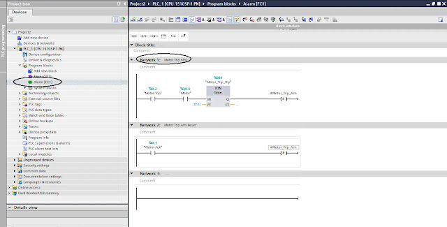
4. Next, you start writing the logic for
alarms. This is because, generally, you have many modes of operation in a
process like auto mode, manual mode,
maintenance mode or semi-auto mode. Depending upon the logic, these modes
can have alarms in it. So, if you are not configuring the alarms first, then
you cannot interlock the system properly in the required mode. Like in the
below image, I have configured the motor trip alarm which is required in auto
and manual mode according to my control philosophy. Also, take care that you
name the section name and rung name appropriately as highlighted by circle in
the image. After configuring the alarms,
you need to link them with hooter if present.
5. Next, suppose
you have two modes – auto and manual.
Start with manual mode first. In manual mode, if alarms are relevant, then link
them with the corresponding outputs. Like in the below image, I have created a
logic for turning motor on manually. Also, do remember to forcefully reset the
buttons according to your condition. Refer the below image for understanding.
There is one main reason to develop manual mode first. Suppose the PLC goes on
site without logic testing. Then at least, the operators there can start the
system manually and check their field devices. This will then help them to
execute auto mode process smoothly.
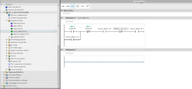
6. Next, start
developing auto mode. Read the control philosophy and develop the program
accordingly. Like in the below image, I have created a small logic to control
the motor according to my control philosophy.
Have a look at
some general points to cover when developing the logic:
1. Properly assign
memory addresses to the variables wherever required for HMI / SCADA graphics.
For best result, assign the variables in groups. If in a group there are two
memory addresses which are spare, then do not use it. Keep it as it is. This
will help when the demand increases in next project to use the spare addresses.
This will help in aligning the addresses in a proper way.
2. If you find
that there are multiple processes with same logic, then use function blocks
instead of writing the logic repeatedly. This will help reduce memory
consumption and also make the program look easier to view and operate.
3. Use a separate to
turn on the outputs by any mode. Then, use the final derived memory variable to
turn on the actual physical output. Like in the example discussed earlier, you
must have seen that I am not turning the motor on directly. In each mode, I
have turned on separate outputs and these outputs will then be linked to the
final PLC output in a separate section.
4. Do not forget
to write general logic like mode selection, alarm reset, button selection,
popup selection etc. It depends on your control philosophy requirement.
5. If there are
valves and pumps which require an on or off delay, use a separate section to
use timers for the required PLC outputs needing timers to operate.
6. When analog
inputs and outputs are used, do remember to first develop it’s logic for
scaling, before starting any logic. Because, you cannot use raw counts directly
in the logic; you will require a scaled variable for that. This step can be
executed before writing alarms.
I have covered
the general principle of developing a PLC program step by step. I have also not attempted to
cover every theory of these types deeply; you can learn it easily once you get
familiar with them. I have just given you an insight of these types of designs.
Once you are done with these, I am hopeful you will be easily able to design
any logic properly. Learn the basics and explore a new type of study in this
type of engineering. It will take some practice and as you go on designing the programs,
you will become more familiar with it.
Thank you guys; I hope you enjoyed reading the
practices normally used for this type of study in industrial automation.


Comments
Post a Comment
If you have any queries, please let me know