How To Read P&ID Drawings
25 Oct, 2022.
In this
post, we will see the concept of reading a P&ID diagram.
In instrumentation and industrial automation, there are many documents which need to be properly interpreted to work accurately. Understanding documents is the first step in creating any project. Out of the many documents that you receive, one of the most important document is a P&ID. It needs to be properly understood for recreating the image of a process in your mind. In this post, we will understand how to read a P&ID diagram.
P&ID diagram:
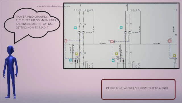
P&ID stands for piping and instrumentation diagram. Simply, suppose you go to your building water pump house, and you want to know how the water is coming from municipality to your house. What you will do generally is go the pump house and observe the pipelines and motors with their connections. You will understand after some time for sure, but it will consume much time. It will be a very cumbersome task. So, instead of manually seeing the whole system, you just need to read a document called P&ID. This diagram will show the drawing of the pipelines, motors, valves and instruments connected with proper flow. It will quickly draw an image of the system in your mind and understand you the whole process from where the water is coming and how it is flowing through the pipes to your home. So, in general concept, it gives you an overall look of detailed piping, instrument location, tank location, utility transfer source and destination, and construction process. This document will then help to understand how the process will look like, flow and complete. It is also a very important document for the programmers to understand process flow, which will help them to design the program accordingly. Have a look at the below image for reference. We will use this in the whole post for studying it.
How to Read P&ID:
P&ID means in general industrial automation is used. So, first keep
the PLC IO list in handy with you. This is the first step in reading the
P&ID. Once you get the IO list, mark the inputs and outputs in the diagram
with a highlighter. For example, in the above diagram, the following IO’s are
used:
Digital Inputs - 199.1LS-01 High-High, 199.1LS-01 High, 199.1LS-01 Low, 199.1LS-01
Low-Low and 101.1LS-01.
Digital Outputs – 199.1AV-01, 103.1P-01 and 101.1DP-01.
Analog Inputs – 101.1pH-01.
Mark the digital inputs with yellow colour for example, digital outputs
with red colour for example and analog inputs with orange colour for example. This
will help in marking the automation related IO’s in the P&ID. Reading a
P&ID starts from understanding the flow of process. For this, just follow
the arrows mentioned in the diagram. Understanding the flow of arrows directly
relates to the flow of process. You first identify the source of flow and then
at last, the destination of flow. Once you become familiar with the flow, you
will get a very clear idea of how the process will work. Also, there are mostly
three types of lines presented in a flow – your
scope, client scope and skid. You can see it in the above image. This also
helps to identify and design the scope of work.
Then identify the IO’s you have highlighted in the image. Generally, LS,
FS, CS etc. these terms indicate a digital switch. LT, TT, FT etc. these terms
indicate an analog transmitter. In the P&ID, there will be two types of
valves – auto and manual. Auto valve will be indicated by AV and manual valve
will be indicated by MV. So, our area of
interest will be to understand only auto valves.
Now, there are many parts where you can see the dotted lines with the
instrument. It starts with one instrument and ends with the other. Don’t refer
the dotted line showing flow of process. It is a different thing. The dotted
lines we are talking about refers to the interlock between the corresponding
instruments. It shows that the instrument is related with the other in either
analog control or digital control.
Once you got through the flow and instruments, you will easily then
understand the whole process. It is just important to identify automation and
non-automation devices. Every instrument has a meaning in the P&ID. If we
go through all of them, then it will be very difficult to understand the
process. So, just clarify the automated-related instruments, as they are the
ones which will finally control the whole plant. Also, every P&ID has
legends in it. Legend means the name and description of equipment, colour code,
tank details and analog instrument details. This helps in understanding the
P&ID more clearly.
I have covered
the general principle of P&ID reading. I have also not attempted to cover every theory of these types
deeply; you can learn it easily once you get familiar with them. I have just
given you an insight of these types of drawings. Once you are done with these,
I am hopeful you will be easily able to understand any P&ID properly. Learn
the basics and explore a new type of study in this type of engineering. It will
take some practice and as you go on studying the P&ID, you will become more
familiar with it.


Comments
Post a Comment
If you have any queries, please let me know