How To Control VFD Through PLC
2 May, 2021.
In
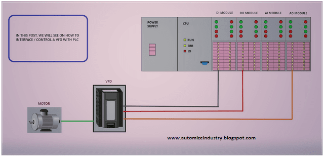
this post, we will understand how to control a VFD through PLC and see
the most commonly used interfaces required for this control. (Click on
the images for a more zoomed view)
A VFD (Variable Frequency Drive) is an automation device which is used to control the speed of the motor. Almost every motor control today will have a VFD implemented in the panel for interface. You can just connect a VFD with a motor and locally program the VFD to control the motion of the motor. Because, VFD is nothing but a control equipment just like a PLC, with a graphical interface on it. It has in-built parameters which a user has to set according to their requirement.
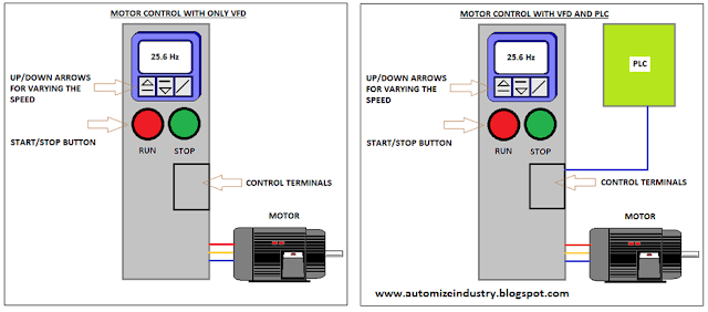
Nowadays, due to use of PLC in industrial automation panels, a variable speed motor will be required to be handled by PLC. But, due to VFD in between; the PLC will control VFD first and then the motor will be controlled by the VFD. See the below image on why we will need to control the VFD instead of the motor through PLC. This is the most basic thing that many beginners fail to understand on why a VFD needs to be controlled by a PLC in order to handle the operation of motor.
If you are using only a VFD, you will have to start or stop the motor through push buttons on the VFD interface. The speed of the motor will be varied through up and down buttons on the VFD interface. This means that all the control of the motor is done locally through the VFD. Now, similar to PLC, a VFD has a set of control terminals with digital inputs and outputs; and analog inputs and outputs. If you are using PLC in the system along with VFD, then all the local activities that we saw earlier in the VFD control will be done remotely by PLC. Why? A PLC is used for controlling field equipment, which is a motor here in this example. A motor is a digital output for PLC. But, there is a VFD in between. So, this concludes that the digital output of the PLC will be a digital input of the VFD (start / stop command) and the analog output of the PLC will be an analog input to the VFD (4-20 mA / 0-10 V speed reference). Thus, all the start and stop of the motor along with varying it’s speed is controlled remotely by a PLC. So, the field equipment becomes VFD here for the PLC.
VFD Wiring with PLC:
So, let us start with hardware interface first. Refer the below image. Generally; digital input, digital output and analog input terminals are used at VFD side for hardwiring interface. Digital input will be used for run command, digital output will be used for providing a feedback that it is running or in trip condition, and analog input will be used for taking speed reference. This is the most common and complete wiring used for any VFD interface with PLC. Sometimes, if application demands, analog output terminal of VFD is also used to provide it’s parameters like running frequency, current, voltage etc. to the PLC analog input terminals.
PLC Program for Motor Speed Control:
As you are controlling the speed of the VFD through PLC, it is important to properly scale the raw output counts from PLC in accordance with the frequency of VFD. If you see the below image as an example (logic written in PLC), the variable AO_PW1_P_FREQ_PV is scaled in the range of 0-500 (50.0 Hz here) for an output of 4000 to 20000 counts (4-20 mA here). Different PLC’s have their corresponding scaling formats and variable formats. You have to set it accordingly. This example is of Schneider-make PLC (M241).
VFD Speed Control Parameters:
Now, let us see the programming parameters that you have to set in VFD. I will take the most common and general used parameters that are required to control a VFD from PLC. In this example, I will use a Schneider-make VFD (ATV312) for reference.
Let us cover all the parameters one by one:
1. The first parameter covers what type of start/stop control you require. Generally, two types are used – 2 wire and 3 wire. 2-wire is the standard example that we have seen earlier; means, only two wires are required for start and stop. 3-wire means the traditional push button type wiring; where the first wire will be common, second wire will be start push button and the third wire will be stop push button. That means, only a pulse at these inputs will latch/unlatch the start-stop logic internally in the VFD. So, you can say that 2-wire type is a toggle type. Potential at both the wires will run the VFD and zero potential will stop the VFD.
2. The second parameter has two parts. The first part shows whether forward or reverse command is to be assigned to a particular digital input of VFD (LI1-LI6 here; six digital inputs). The second part shows that if 4-20 mA is selected as speed source, then what will be the minimum input current and what will be the maximum input current.
3. The third parameter covers the type of analog output required in hardwiring and what logic is required in giving the output.
4. The fourth parameter covers what will be the logic required for giving digital output to PLC.
5. The fifth parameter is the access level; required to set some other important and critical parameters in the VFD.
6. The sixth parameter allows you to choose the source of speed reference.
7. The seventh parameter allows you to choose the source of command
reference.
In general, if you are trying to run the VFD through PLC,
these are the most common parameters will automatically bring the VFD control
in your hand. Other parameters are by default set in it and can be modified
according to the application. You can now relate the parameters with the
hardwiring interface that we had studied earlier. They both are inter-related
and will indirectly do your job. Just search the parameters and in case it does
not work, you can contact the VFD manufacturer for other parameters required.
Every VFD has their own set of parameters and varies from manufacturers to
manufacturers.
I have covered the general practices used in controlling a
VFD through PLC. I have also not attempted to cover every type of VFD deeply;
you can learn it easily once you get familiar with them. I have just given you
an insight of these types of controls. A great programming understanding is
required by the engineer who is controlling the overall system of PLC’s and
VFD’s. Learn the basics and explore a new type of study in this type of
automation.
Thank you guys; I hope you enjoyed reading the practices normally used for this type of study in industrial automation.


Thank you so much for the information that you sent to me the other day. It helped me greatly and saved me from making all kinds of mistakes.
ReplyDeleteLove from codienvn.com
nivo
thước kẹp
insize
Thank you so much for the information that you sent to me the other day. It helped me greatly and saved me from making all kinds of mistakes.
ReplyDeleteLove from codienvn.com
nivo