Output Wiring and Resolution of Incremental Encoders
8 Nov, 2020.
In this post, we will understand the general theory of incremental encoder wiring outputs and it’s resolution.
Hello engineers. Welcome back to our study. I hope you enjoyed reading the first part on understanding the encoders in general.
Let’s get a look now on how to wire an incremental encoder and how is the resolution calculated in it.
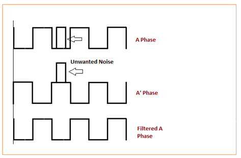
For simplicity, we will consider the most commonly used types – rotary encoders. These encoders supply two square wave pulses offset by 90° A and B, and a reference pulse Z (homing/zero signal) as well. In order to suppress spurious pulses, complementary (inverted) outputs are also provided namely A’, B’ and Z’. These signals are the exact opposite of the normal outputs provided. I.e. if A is 1, then A’ is 0. This provides differential signals for reduced noise and greater drive capability. The advantage of normal and inverted signal transmissions is that filtering of unwanted signals is possible. If a noise pulse occurs, it will be induced equally on all channels. Subtracting the normal and inverted encoder signals from each other eliminates the noise pulse.
The lagging and leading signals in phase relationship determines the direction of rotation. That means, if A signal comes first, then it’s a clockwise direction and if B signal comes first, then it’s an anticlockwise direction. Encoders can provide a once-per-revolution pulse (often called index, marker, or reference) that occurs at the same mechanical point of encoder shaft revolution. This pulse is on a separate output channel (Z) from the signal channel or quadrature outputs. The index pulse is often used to position motion control applications to a known mechanical reference. Refer the below images. The first image shows the three main types of encoder outputs and the second image shows the use of complementary signals.
Output Voltage Types of Encoders:
Now, coming at the output voltage types, these are the following types of outputs:
1. Open Collector (TTL):
This is one of the simplest and economical output methods. It is operated at a voltage of 0-5 V. They are basically based on NPN (sinking) transistors. When the transistor is on, the encoder acts as a current sink. When the transistor is off, the output is left floating (open). Because the transistor output is left open, open-collector drivers need to be used with an appropriately sized pull-up resistor. This resistor “pulls” the signal down, switching the output on and off to generate the square-wave signal.
This method is only suitable for low-noise environment and shorter cable lengths. It works best at lower output resolutions.
2. Push-Pull (Single Ended):
Adding to TTL logic, they implement PNP transistors also. So, due to usage of both the sinking and sourcing circuits, they are more efficient than TTL output encoders. But, one thing to consider is that they don’t provide complementary outputs (A’, B’ and Z’). They operate at a voltage range of 0-30 V. By eliminating the pull-up resistor used in open collector outputs, push-pull outputs use less power and are therefore good options for battery-operated designs.
3. Push-Pull (Differential Line Driver):
This is the one of the most common and widely used encoder types. Adding to push-pull single ended drivers, they provide complementary outputs (A’, B’ and Z’) too. They too operate at a voltage range of 0-30 V.
Encoder Wiring to PLC:
Let’s have a look at the commonly used wiring types. The simplest type of wiring used is flying-lead wiring. It consists of individual wires running from the encoder connector. You can also define it as a simple parallel wiring. But it is more prone to electrical noise. If you go advanced than this, you will encounter multi-conductor cable wiring. It collects multiple wires together in a single bundle with strength elements, cladding, and factory- or user-installed couplers. Multi-conductor cables can be either stranded or solid core. They can be a good solution for low-noise environments and distances on the order of a few meters. Now, twisted-pair cabling works best for differential output encoders. The effect of the twist is to cancel inductance and minimize crosstalk. Each twisted-pair can conduct the signals for a given channel, with one wire of the pair carrying the main signal and the other carrying the complement. Twisted pairs are essential for high-noise environments and can support runs as long as 40 m.
But, only wiring won’t do. You have to learn proper grounding techniques in encoder, because noise can disrupt the counts received at the PLC. First of all, after doing the necessary wiring, see to it that the encoder cable does not run close to power cables. Provide shielded wires to the encoder and avoid ground loops as much as possible by grounding cables on one side only. One of the most common mistakes users make is improperly grounding the shielding—either grounding it unnecessarily, which creates a ground loop, or failing to ground it when they should. The correct method depends on the cabling assembly and connector type. In general, an encoder is grounded to its mounting, making it unnecessary to ground the shielding so long as the shielding is contacted to the encoder. If the encoder is not grounded, then the shielding must be provided; for example, by adding a separate wire to the encoder case that would be grounded to the drive/controller.
Encoder Resolution CPR:
Resolution is a term used to describe the Cycles per Revolution (CPR) for incremental encoders, or the total number of unique positions per revolution for an absolute encoder. Each incremental encoder has a defined number of cycles that are generated for each full 360 degree revolution. These cycles are monitored by a counter or motion controller and converted to counts for position or velocity control. Often, users get confused in defining the encoder output. For that, it’s necessary that you understand the below subject for properly defining an encoder resolution. There are three types of resolution theories:
1. Native resolution:
This is the most straightforward calculation that you will get. If you remember my first article, the number of slots counted generates pulses. This is nothing but native resolution. So, if there are 400 slots in the disk, then the encoder CPR will be 400.
2. Interpolation:
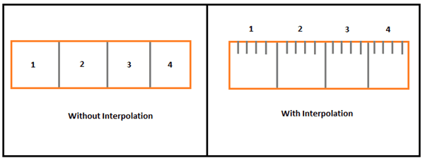
With the advance of electronics, it is possible to increase the resolution by converting the original one into a new factor through the use of in-built chips and modules. This technique is named as interpolation. In reality, manufacturers employ an array—many LEDs and sensors. The array presents multiple views of the lines on the disk to the onboard signal processor (which is part of the encoder module). If the true position is somewhere between two lines, the signal processor can interpolate to find that position.
Refer the below image. You can imagine it as a scale; which is only marked with inches and fractions are added between each inch to read smaller measurements. That means, if there are 400 lines on the disk and the internal module is interpolating, then it would be 400 multiplied by 4; 1600 PPR.
Interpolation is also used because at one point of limit, you cannot physically extend the lines any more on the disk.
3. Resolution Multiplication:
This happens at the controller or PLC. Due to use of quadrature signals (A and B), many controllers have the option to multiply the final counts coming out of encoder into a large quantity. This is referred as the counting method in PLC language. Every PLC manufacturer has it’s different way of multiplying and handling the encoder output counts to give us the final PPR.
Encoders come in various digital formats. They are categorized in terms of bits. I.e. 12-bit, 13-bit, 14-bit and go maximum up to 16-bit. So, 2 raised to 16 gives us 65535. It depends on the number of slots present in a disk. Remember; in a particular revolution, once the last count is reached, it again starts counting with zero. It is the job of the PLC to convert it into continuous counts through the use of it’s internal configuration and logic.
This lesson has been a basic introduction to the general theory of encoders. The ways the encoders are built differ between manufacturers and models, so I have just covered general principles without enough detail to implement them in any given system. I have also not attempted to cover every type of encoder. Each manufacturer has unique ways of handling measurements, and there are many other sorts of encoders that we have not included here.
Thank you guys; I hope you enjoyed reading the practices normally used for this type of study in industrial automation. If you have any views or know some more methods, then I would be happy to get a comment from you.


I read your blog content which is very helpful for me.So i really thankful to you for this content.
ReplyDeleteElectrical And Automation