Difference Between Isolated and Non-Isolated PLC Modules
11 Oct 2020.
In this
post, we will clarify the difference between isolated and non-isolated PLC
analog modules; and understand why isolation plays an important role in 4-20 mA
current loops. (Click on the images for a more zoomed
view)
Hello programmers. You all must be
familiar with the two widely used types of analog signals – 0-10 V and 4-20 mA.
Of these, the most popular one that is used is the 4-20 mA type one. The wiring
is simple; you have transmitters where only two wires are needed
(loop-powered). It can be run over long distances with minimum drop; voltage
drops much across long distance wires as compared to current drop. A varying
current loop load impedance will not affect the signal if it does not exceed
required component limits. Electromagnetic interference affects current loop at
a much lower rate as compared to voltage circuit.
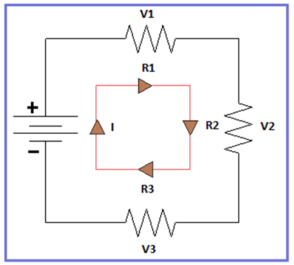
All the above advantages can be explained by simple Ohm’s law – V=I*R. Let’s see the below image. The circuit consists of a power supply and three loads. The power supply will give the voltage required to drive the current loop. Through current passing across each load, voltage drop occurs each of them and will vary according to the resistance available. However, current remains the same in the whole circuit. That is why; current is the most reliable source of information available for data.
Now consider the below image for the
understanding of current loop. The sensor provides the physical signal and the
transmitter acts as a transducer which converts this physical signal into
electrical current signal. For this signal to be produced first, a power source
is required. The loop is nothing but the wiring which carries the signal from
transmitter to receiver and then back to it. The value of the cable resistance
is directly proportional to the distance of transmission. If 0-10 V is
transmitted over long distance, there will be a drop in voltage due to
resistance of the cable; and the signal received will not be accurate. So, 4-20
mA is the main reason for it’s wide scale use.
But every technology has it’s pros and cons. The current type has high power consumption compared to other analog signal types. Increasing circuit load resistance will reduce the supply voltage available to power the transmitter that is generating the current signal. One of the major concerns of 4-20 mA is non-isolation. This single reason affects the use of this signal. We will investigate this theory and understand how an isolated PLC module improves the overall efficiency of the signal transmission as compared to a non-isolated PLC module.
Theory of analog isolation:
What is isolation in PLC?
First, what is isolation? Isolation is
used to protect circuitry and human beings, break ground loops, and improve
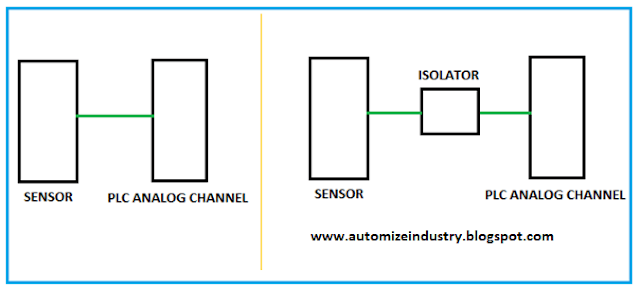
common-mode voltage and noise rejection performance. See the below image. The left-hand
side image shows that a sensor is directly connected to analog input channel;
whereas the right-hand side image shows that the sensor is connected to the
channel via an isolator. The isolator protects the channel from any power/noise
fluctuations on the sensor side. It only filters the proper analog signal to
the channel and removes the spikes and fluctuations in it’s input side.
Ground loop leakage in 4-20 mA:
It’s other important use is to avoid
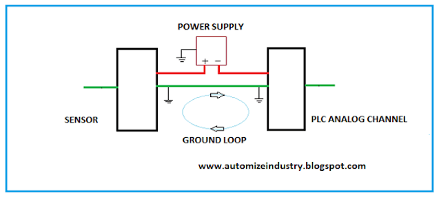
ground loop leakage. A ground loop current is nothing but the current flowing
from one signal ground in a circuit to another signal ground at a different
voltage potential. Most analog (4 to 20) mA loops are grounded at a single
point. Problems occur when there is more than one grounding point because earth
potentials will not be the same. This means current will flow between earth
points causing errors or noisy signals. This causes unpredictable signal
fluctuations and will often average the process signals, which causes reduction
in actual input/output with respect to channel. It can be like; you are
providing 16 mA from PLC analog output, but the field device is functioning at
12 mA. This problem is mostly faced in loads with high impedance. So,
installing an isolator in between will eliminate ground loop leakage, as the
isolator isolates channel and ground.
What are the different types of isolation?
PLC channels can be isolated either by
connecting an isolator in the current loop circuit; or using an isolated PLC
module. Isolation is mostly achieved by galvanic isolation. Galvanic
isolation is the principle of physically and electrically separating two
circuits, so that there is no direct conduction path, but data and power can
still be exchanged. This is typically achieved by using transformers,
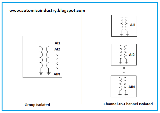
optocouplers, or capacitors. Refer the below image for understanding. As we
know an individual isolator, let’s investigate an isolated PLC module. There
are two types of isolation generally used in PLC modules – group isolation and
channel-to-channel isolation. In group isolation, all the channels are grouped
together to share a single isolation barrier, including power isolation and
signal isolation. But here, common-mode voltage difference arises between
channels in the group; meaning they should be placed in same zone. To eliminate
this problem, channel-to-channel isolation is used. In this, every channel has
it’s individual power isolation and signal isolation. This means that channels
are isolated from each other and any damage to a particular channel won’t
affect the other ones.
Isolated vs non-isolated analog input:
A common question most programmers ask
is how to choose between an isolated and non-isolated analog input. Mostly, in
all the PLC’s, when you choose a module between isolated and non-isolated;
remember that non-isolated means there is no isolation between channels and
isolated means there is isolation between individual channels. Remember that
channel to ground isolation is provided by default.
I would not go deep into ground loop
theory, isolation methods and need for isolation. It is very vast and would
take a lot of time for you to study. But it’s important to first understand the
concept behind isolation in analog circuitry. It basically protects the channel
from external damage. Also, this does not mean that you don’t have to use a
non-isolated module. It is cheaper than an isolated module and will work
properly too; provided the loop design has been thoroughly analyzed and made
accordingly, to avoid problems that are only realized when trying to get the
system up and running. There are numerous electrical methods in grounding the
system properly and securing it with safety too, which will properly utilize
the non-isolated module. The topic that I have written covers both analog
inputs and outputs.
I have covered the general theory
related to isolation and the difference between isolated and non-isolated
modules. I have also not attempted to cover every type of features deeply.
I have just given you an insight of this type of study. Learn the basics and
explore a new type of theory in this type of automation.
Thank you, guys; I hope you enjoyed reading the practices normally used for this type of study in industrial automation.


Comments
Post a Comment
If you have any queries, please let me know