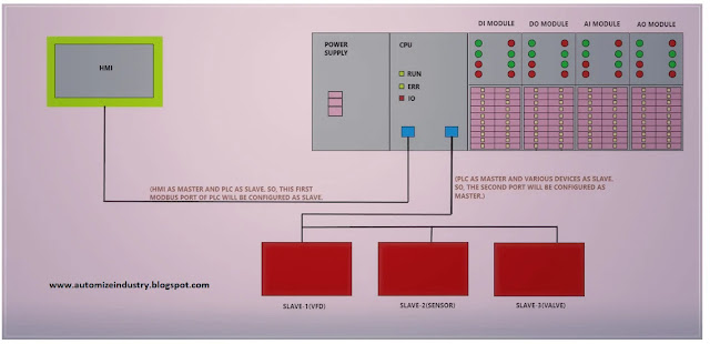
Troubleshooting Modbus Communication in Schneider PLC
14 June 2020.
In this
post, we will cover practices used in various Schneider PLC’s for
troubleshooting Modbus communication. (Click
on the images for a more zoomed view)
Hello guys.
Welcome back to our study. I hope you enjoyed reading the first part on the
general theory related with Modbus communication. It was necessary to inform so
that you can read this post easily.
Let’s get
a look now on how to find problems in Modbus communication in various Schneider
PLC’s. Here, we will mostly look at the problems found in coding; because you
can refer the first post first whenever you are trying to find the Modbus
communication fault. The contents covered in first post will generally solve
your issue in first attempt. Guys don’t just start jumping into your program in
first attempt. As a programmer myself, I have learnt that always jump in the
basic criteria first.
How to check Modbus communication in Schneider PLC's?
Machine Expert Basic (M221/M200/M100 series):
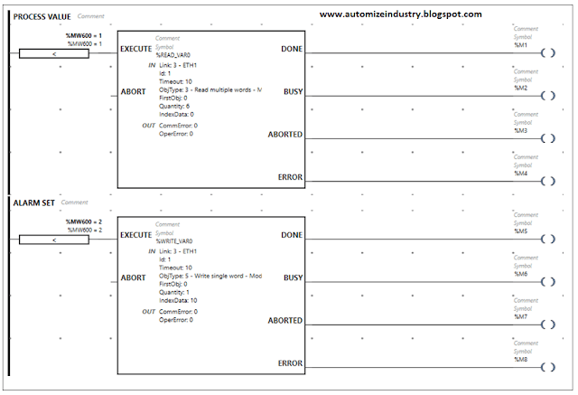
In Schneider
PLC’s, read_Var and write_Var blocks are used
to communicate. So, even in this PLC, you can refer the below image. The first
and foremost thing you should look for is the configuration of block. Verify
whether the set parameters (Link, ID, Object Type, First Object, Quantity,
Index Data) are correctly fed or not. It is possible many a times that the
device that you are communicating has only 3 registers, but you have entered
the length as 4. This will throw an error and won’t communicate. So, accurately
feed the data in the block. You must know what data you are going to read or
write with respect to the device. Object type is the type of function code;
first object is the address of the first register you are communicating with;
quantity is the number of registers you want to communicate and index data is
the first memory address in PLC where the data will be communicated. For
example, in the below image of Write_Var block, data from
%MW10 address of PLC will be written in register address 40001 in the device.
The block has four
outputs, which is used for troubleshooting. Make sure a single address is not
used anywhere else (don’t repeat multiple times). Refer the help file in the
software for CommError and OperError outputs.
When the block is not communicating, it will show an error code in decimal
format, which you must decode in binary format for exact fault. The Done bit
will be true if communication is proper. So, the read_var error codes and
write_var error codes must be understood properly for troubleshooting.
Execute pin requires
a pulse to execute the function. Remember, each block must be executed
separately after an interval. You can refer the image. If multiple commands are
executed at the same time, then the communication will not happen. This is
because Modbus communication sends only one request at a time.
If you
want to save time in writing these blocks, then IO Scanner option
is also provided. Refer the link below given by Schneider Electric, which shows
how to set it up properly. This is the simplest option compared to the bulky
codes that we write.
https://www.youtube.com/watch?v=mLQponN3lPc
Refer the
below image for an overview.
Overall, you just must see that the addresses are not repeated anywhere, and you execute only one block at a time.
Somachine V4.3 (M241/M251/M218/M238/M258 series):
Even in this PLC's, read_Var and write_Var blocks are used to communicate; so the M241 Modbus RTU logic is same here too. You can refer the below image. The execution is same as discussed earlier. The only difference is that we have used an additional ADDM block here. The ADDM function block converts a destination address that is represented as a string to an address structure. You can use the address structure as an entry in a communication function block. In the below image, the Modbus port used is 2nd no and the address of the slave device is 6. So, the format is ‘2.6’. The address structure output a1 is then used as reference for the communication blocks. The variable in_sv is a single memory address as we are reading only one register. If you are communicating multiple registers, then define an array variable here. And as you can see, execution of blocks takes place at different intervals. You can refer the help topic in the software for these communication blocks and it’s various formats.
If you
want to save time in writing these blocks, then IO Scanner option
is also provided. Refer the link below given by Schneider Electric, which shows
how to set it up properly. This is the simplest option compared to the bulky
codes that we write.
https://www.youtube.com/watch?v=rTNlMsdnTZ0
You can
visually see in the Device Tree whether the device is
communicating or not. Green color means the device is communicating and red
color means the device is not communicating. You can also get status of the
variable communicating in this block, which will help you in further
troubleshooting.
Unity Pro / Ecostruxure Control Expert (M340/M580/Quantum/Premium series):
Even in this PLC's, read_Var and write_Var blocks are used to communicate (This PLC range usually uses NOM0200 for serial communication). You can refer the below image. The execution is same as discussed earlier in Somachine V4.3 section. You can refer the help topic in the software regarding these blocks and the various allowable formats used for input and output variables.
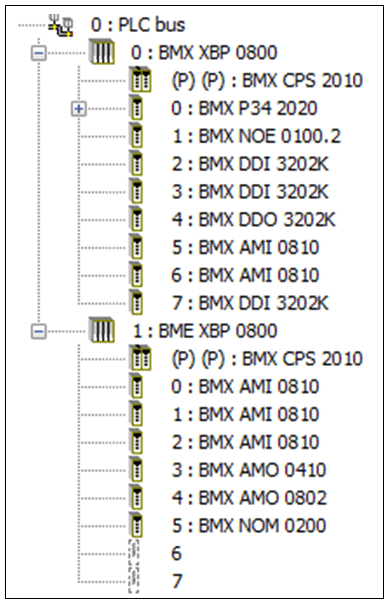
Let me
explain the how the address structure was defined. Refer the below image, which
shows the configuration of PLC used. The Modbus module BMX NOM 0200 is in 5th slot
of 2nd rack (Rack ID is 1). There are 2 channels in this module,
and I had used 2nd port (Channel 1; Channel 0 is the 1st port).
The ID of Modbus device was 2. So, the structure comes as ‘1.5.1.2’; which
means Rack No. Module No. Channel No. Slave ID. You can refer the help topic in
the software for ADDM block and the various allowable formats for address
structure.
One more
thing different here is the GEST variable (MNG_PARA5).
It is the management parameter, which is an array of 4 elements. You just must
define timeout time in the 3rd element. The remaining 3
elements are for troubleshooting. You can refer it’s help topic in the
software. My personal advice is that keep the value of timeout as 0 if you are
using Modbus RTU. Once the communication fails, then we must either power cycle
the PLC or download the program once again to reinitialize the block. So,
keeping this value as zero will solve your issue. Once communication
establishes once again, then it will automatically reinitialize the block.
There are no such criteria for Modbus TCPIP.
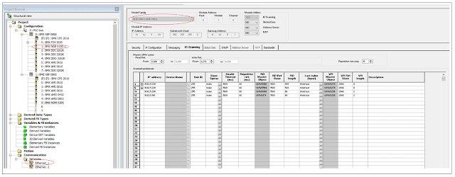
If you want to save time in writing these blocks, then IO Scanner option is also provided. But it is available only for Modbus TCPIP. Refer the below image. The feature is available by double clicking the Ethernet port shown in red circle (Ethernet_1). Basically, if you refer the image; the Model Family tab selected in the top (in red circle) is BMX NOE 0110.2 which denotes the use of BMX NOE 0100.2 module (in red circle) that I used in program. I had configured this module in Ethernet_1 slot.
You must
define proper device address in the IP address slot with
it’s Unit ID. RD Master Object means the PLC
address where the data will be written, and RD Ref Slave is
the register address in the slave device from where you want to read. Enter
appropriate length of data to read in RD Length tab. Similar
is the standard for writing objects. Make sure you don’t overwrite memory
addresses; otherwise, communication won’t happen.
This lesson has been a basic introduction to the most common sorts of Modbus communication techniques used in PLC-based applications. Each of the types covered here has its quirks, and the ways the software configuration is built differ between manufacturers and PLC models, so I have just covered general principles without enough detail to implement them in any given PLC system. I have also not attempted to cover every type of device. Each manufacturer has unique ways of handling communication, and there are many other sorts of techniques that we have not included here.
Thank
you guys; I hope you enjoyed reading the practices normally used for this type
of troubleshooting in industrial automation. If
you have any views or know some more methods, then I would be happy to get a
comment from you. I will surely reply and help in your queries or other
techniques.


Your useful blog is appreciable. We are working on relevant area PLC.
ReplyDeleteThanks for this post.