Solve Communication issues between HMI and PLC of Schneider Make
21 June 2020.
In this
post, we will cover the basic topics on how to troubleshoot problems faced by
programmers in establishing communication between a PLC and HMI of
Schneider-Make. (Click on the images for a more zoomed
view)
Hello programmers. Here we will discuss the common mistakes made by programmers in establishing proper communication between a PLC and HMI of Schneider-Make. We will discuss here the two widely used protocols; Modbus RTU and Modbus TCPIP. The HMI software we will cover is Vijeo Designer and the PLC software that we will cover are Ecostruxure Machine Expert-Basic, Somachine V4.3 and Unity Pro/Ecostruxure Control Expert.
Before moving ahead,
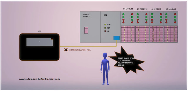
refer the below image. When HMI is not communicating with PLC in Schneider
platform, then it will show as yellow triangle besides the display and popup
the message below.
Basic steps involved in checking communication between PLC and HMI:
We will divide our lesson into three topics. The topics
here means, the three types of issues and it’s solutions.
So, without wasting any time, we will jump to our study and
review each case normally faced.
Proper cable configuration and cabling:
1. The basic and foremost thing to check is this topic. We go to all the advanced steps and then we realize that it was this basic thing which we forgot to check. Always check the type of cable which you are using for communication.
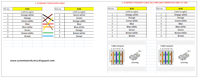
2. Now, let’s look at the cable configuration used for Modbus TCPIP and Modbus RTU (RS-485 hardware). Refer the below image for understanding. The first image with three wiring types shows the practice used for Modbus RTU configuration. It is a standard Modbus RTU RJ45 pinout. The second image with two wiring types show the practice used for Modbus TCPIP configuration. If there are multiple PLC’s and a single HMI, then refer my topic (Troubleshooting Modbus code Schneider PLC - Part_1_General Practices in Modbus) for proper cabling practices, if the protocol used is Modbus RTU. Whenever you are thus searching for Schneider Modbus cable, refer this for proper information. Modbus TCPIP is simple and just requires a series of Ethernet connections on a hub switch with distinguished IP address.
Proper configuration in software:
1. The next step is to check the communication settings done in software. Ensure that the settings in PLC and HMI are proper; otherwise, communication won’t happen.
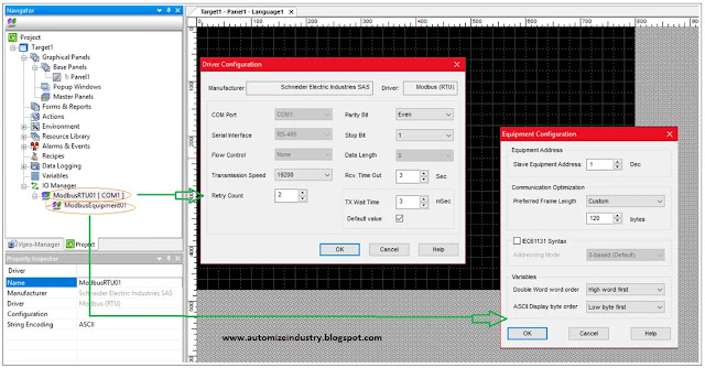
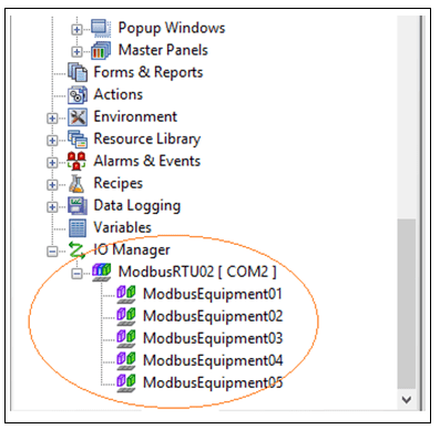
2. Refer the first image. We will first check Schneider HMI programming. For Schneider HMI programming, Vijeo Designer software is used. Vijeo Designer is the only Schneider HMI software available in their platform for touch screen HMI panels. It shows the settings available for Modbus RTU. The settings shown are default one, which appear when you select this protocol. Ensure that the transmission speed, parity bit, stop bit and slave equipment address is correct or not. Also verify whether you have connected the cable in COM1 or COM2. When there are multiple slave devices connected, then the settings will be as below in second image. Only equipment address will differ. Make sure they don’t clash with each other. The third image shows the settings for Modbus TCPIP. Make sure the IP address of target (HMI) and the slave device are not similar. Also ensure that the Unit ID of slave device is proper. Multiple slave devices will show same settings as referred above. IP addresses and Unit ID will differentiate between them.
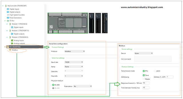
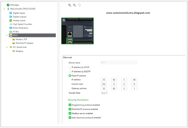
3. Now, let’s move ahead to PLC configuration. Refer the first image. It shows the settings available for Modbus RTU in Machine Expert - Basic. Ensure that the baud rate, parity bit, stop bit and address are correct and match with that in HMI. Also verify whether you have connected the cable in SL1 or SL2. The second image shows the settings for Modbus TCPIP. Make sure the IP address of PLC is similar with the equipment configuration in HMI.
4. Now, let’s move ahead to Somachine V4.3 / Machine Expert. Refer the first image. It shows the settings available for Modbus TCPIP. Ensure that the IP address matches with that in HMI. The second image shows the settings for Modbus RTU. Ensure that the baud rate, parity bit, data bit, stop bit and address are correct and match with that in HMI. Also verify whether you have connected the cable in SL1 or SL2.
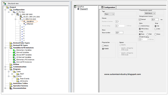
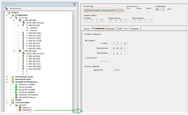
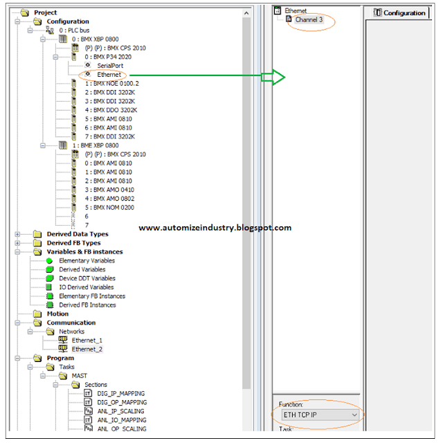
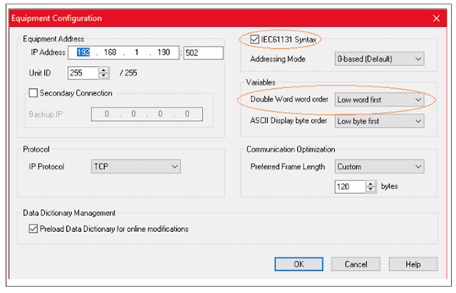
5. Now, let’s move ahead to Unity Pro / Ecostruxure Control Expert. Refer the first image. It shows the settings available for Modbus RTU. Ensure that the settings match with that in HMI. The second image shows the settings for Modbus TCPIP. Ensure that it matches with that of HMI. Also ensure the settings in third image, which most people forget to see.
Proper addressing of variables:
After understanding
the above two methods, let’s move to third method. It deals with proper
addressing of variables. We either enter improper address (in HMI, it will be
%MW100 and in PLC, it will be %MW101) or keep the wrong format of variable (in
HMI, it will be INT and in PLC, it will be REAL). Machine Expert – Basic
software has one-to-one addressed, and you can easily troubleshoot variable
properties. But, in Somachine V4.3 software, the addressing is same for integer
values; but different for double-integer and real values. For example, if the
PLC address is %MD50 in real format, the HMI address should be %MF100 (the
double of PLC address). The addressing is also same in Unity Pro software.
Refer the below image for an example of these three software. It shows various
variable properties in HMI. Ensure that you have selected the correct Modbus
Equipment in variable properties.
Refer the below image,
which you have seen earlier too in the topic. Unticking IEC61131
syntax will allow you to enter the variables in old Modicon format
(40001 instead of %MW0). Keep double word order option as low
word first.
I have covered the general principles which normally are followed to troubleshoot communication issue. I have also not attempted to cover every type of device. Each manufacturer has unique ways of handling problems, and there are many other sorts of solutions that I have not included here.
Thank you,
guys; I hope you enjoyed reading the practices normally used for this type of
troubleshooting in industrial automation.








Nice blog...Indication Led Light Supplier in Chennai
ReplyDelete