HART Configuration in Schneider PLC
2 August, 2020.
In this
post, we will understand how to configure a HART device in a Schneider (M580)
PLC.
Hello programmers. Welcome back to our
study. I hope you enjoyed reading the first part on understanding the HART
protocol in general.
Let’s get a look now on how to configure a HART device
in a Schneider PLC (M580).
First of all, the most crucial
requirement is a proper DTM/DD file as discussed in the first part. Be it any PLC, an improper DTM/DD file of the HART
device cannot help you make a connection with it. To find that proper file, you
need to be well versed with the terms – HART universal revision and device
revision. In simpler terms, you can co-relate it with a firmware version of the
PLC. If you read the technical documentation of that device, you will find it’s
default HART universal revision and it’s own revision number (device revision).
They have options to select the revision according to your needs. You can set
them via a HART communicator tool or manually by entering the parameters in the
device menu shown on it’s display.
Let me explain you with the
device that I have used here for study. I have used Rosemount 3051-T pressure
transmitter (Emerson-make), which is
HART-enabled. Refer the below image. The default settings in this device are –
HART revision 5 and device revision 9. If you visit the website of Emerson for downloading the DTM file,
then you will find various versions of all the devices. Selecting the right one
requires sound knowledge of the specifications of device. When you download a
given link, most of them have a readme
file in it; which shows the supported devices in the DTM file and other
information related to HART communication. You can use it for confirmation.
Many a times, you cannot find a DTM file for a specific device; you can then
use a general DTM file of that manufacturer or confirm with them about the DTM
file for any issues.
After you have installed the software (DTM file setup), you have to update this DTM file in the PLC software. Without updating the DTM catalog, you cannot see this file in the software. For the PLC which we are referring here, use Unity Pro V13.1 or above. The software versions mentioned are stable and proper for HART communication. Now, refer the below video.
I will
explain it in the following steps:
· In the Tools
option, go to Hardware Catalog.
· Then, go to DTM catalog
inside it. You can see four sub-topics
under it – Device Types, vendors, groups and protocols. In
the protocols section, go to HART. I had already updated the DTM
file earlier; that’s the reason the device name is showing here (3051 HART 5). For first timers, you
will find that the device type you want is not installed. So, click the Update button below. After updating,
you will find the device name. This indicates that the device DTM file has been
installed successfully in the PLC software.
After the DTM has been successfully installed, you can now assign to it any PLC channel for use. Refer the below video.
I will
explain it following steps:
· We will use BMEP582040
CPU for study. The security features are initially disabled in the CPU. You
will need to unlock it.
· Now, set the IP address of the CPU. When you validate it,
it will ask for a service to be enabled (TFTP). So, unlock / enable all the
security options and tick all of them as shown.
· Then, add the BMEAHI0812
module in the slot required. Only 4-20 mA option is available in this module as
per HART protocol. You can scale the raw counts as required by you.
· Now, go to DTM
Browser in Tools option. Right
click the BMEP58_ECPU_EXT option and
click Add. You have to add the
analog module here. Select the module as shown and add it.
· Double click the BMEP58_ECPU_EXT
option. It will open the communication settings for this CPU. Here, first set
the Channel properties; the IP
address of your desktop. If not set properly, then you won’t be able to go
online in the HART device. Then, click BME_AHI_0812.
In the address setting tab, you have
to set the IP address of the module and it’s position in the CPU system. M is the notation for it’s local CPU
position and C is the notation for
it’s remote CPU position. Here, we used Mx80_02;
as our module is located in the 2nd slot of the local rack.
· Now, double click the BME_AHI_0812
option in the distributed bus as shown. It shows the overall HART settings
of the module. In the process data
tab, you can define which variables you want to read from the device. By
default, four variables are read from a device – PV, SV, TV and QV. In the parameter
configuration tab, you can define which channels are to enabled / disabled
for HART communication. In the security
tab, you have to disable the access
control option. This practice is normally done because sometimes, some
screens in the HART device don’t show proper records; when you go online in it.
Disabling this feature allows you to fully access all the windows inside the
HART device.
· Right click the BME_AHI_0812
option and add the HART device (DTM) in the channel you want.
After the PLC has been assigned with HART settings, you can now view it online. Refer the below video.
How to View HART device online in Unity Pro
I will
explain it in following steps:
· Right-click the module where the device has been connected
and click Connect. The module will
be highlighted in bold as shown in video.
· Again right-click the module and go to Device Menu -> Additional Functions -> Transfer to FDR Server. FDR
stands for Fast Device Replacement.
This service stores network and operation parameters of devices on the network.
If a device is replaced, the service automatically configures the replacement
device with parameters similar to those of the removed device. It is essential
to transfer the latest parameters to FDR server in the PLC; otherwise the bus state LED in the analog module will
blink and HART communication won’t happen properly.
· Right-click the channel where the device is connected and
click Connect. The device will show
as highlighted in bold; if the connection is proper.
· Double-click the device and you can see the overall
parameters of the device as shown in video. You can even configure the device
from this window.
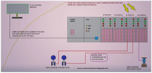
In short,
you can overall control the actual device from just sitting in the centralized
PLC room and even configure it, if required, without going in the field. This
reduces your overall installation time and provides a greater control in the
system. Each and every parameter of the device can be viewed here through HART
communication.
This lesson has been a basic introduction to the general
theory of HART communication. The ways the PLC analog I/O modules (HART-based)
are built differ between manufacturers and PLC models, so I have just covered
general principles without enough detail to implement them in any given PLC
system. I have also not attempted to cover every type of device. Each
manufacturer has unique ways of handling measurements, and there are many other
sorts of instruments that we have not included here.
Thank you guys; I hope you enjoyed reading the
practices normally used for this type of study in industrial automation. If you
have any views or know some more methods, then I would be happy to get a
comment from you.


Comments
Post a Comment
If you have any queries, please let me know