HART Protocol
23 August, 2020.
In this post, we will understand the HART protocol
used in industrial automation. This post is divided in two parts. Our first
part will cover the general theory of HART communication. In the next part, we
will configure HART protocol in Schneider PLC for practice.
Hello guys. In this post, we will study about
HART communication; which is a very advanced type of protocol used in
industrial automation. It is an advanced version of typical analog wire
signalling and it’s benefits are immense and programmer-friendly.
Before starting, let me explain why this type of
signalling is preferred over traditional analog signalling for large scale
plants.
A typical analog device transmits/receives data in two types of hardware signals – voltage or current. Voltage comprises 0-10 V and current comprises 0-20/4-20 mA. PLC inputs/outputs this data in the form of raw counts and the programmer has to scale it accordingly in his program, to match with the actual process value in his display system. Now, as generations passed, a need demanded to just overview and set that device by just sitting in your centralized PLC room. Open communication was the need of the hour and with so many third-party devices being integrated in a particular system, complexity increased. Most of the automated plants were based upon the proven 4 mA-20 mA wiring concept and which provided only the main measured value on the current loop of the standard signal. More process information and digital information was required from these devices as time progressed and industries started to expand.
This gave rise
to HART communication. All these requirements were fulfilled in this protocol.
HART Communication:
HART stands for Highway Addressable Remote Transducer.
It superimposes digital information at a low level on the top of a 4-20mA
signal, which enables bi-directional communication between smart field
instruments and host systems (PLC/DCS or handheld communicator) and also
provides additional information from the device. It includes device status,
diagnostics, extra measured or calculated values etc. This technology makes the
system extremely reliable to use when you are commissioning or calibrating
numerous amount of field devices for continuous online diagnostics. It may
prove costly for a small-scale system where you have only some amount of analog
devices; but it proves handful for a large-scale plant where there are abundant
analog devices and a visit to the field proves time-consuming, hectic and
inefficient.
Frequency Shift Keying:
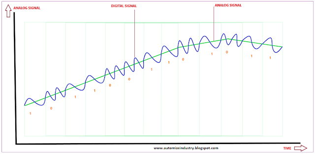
Basically, HART works on Frequency Shift Keying (FSK) method;
which allows digital signal to be superimposed on analog signal. Now, refer the
below image for study.
A digital signal is made up of
two frequencies – 1200 Hz and 2200 Hz; representing bits 1 and 0 respectively.
These digital signals are directly imposed on the standard current signal,
which provides both the analog and digital signals simultaneously. The digital
FSK signal is phase-continuous and since the average value of this signal is
zero, it doesn’t affect the transmission of analog signal. A minimum loop
impedance of 230 W is required for communication. This protocol allows the host
application to get two or more digital updates from the device per second from
the field device. All this allows the user to get both the analog and digital
data continuously without any interruption.
HART communication works on master-slave protocol. It means the field device (slave) will respond to the host application (master) only when asked to. A master will initiate the request for variables and the slave will respond accordingly and communicate with the master. This is the most common method used for communication. A drawback of this method is that if a HART device detects a failure condition in itself or the process; the HART device cannot communicate this information to the host unless the host specifically requests that information from the device. To overcome this drawback, another mode called burst mode has been introduced; which enables faster communication (3-4 data updates per second). In this mode, the slave device continuously updates data (bursting) with the master without it’s command (e.g. the value of a process variable). The master receives the data at a much higher rate until it asks the slave to stop bursting.
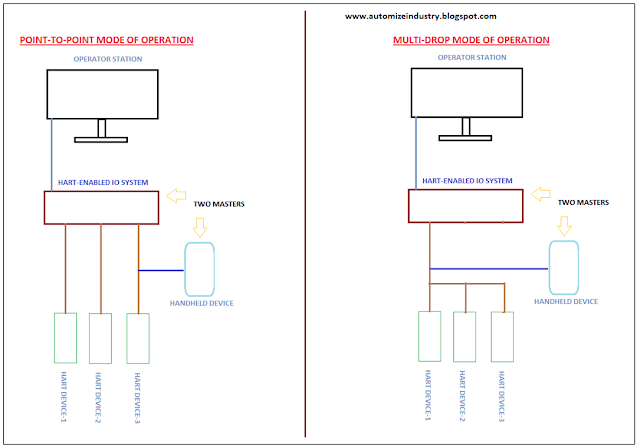
Point to Point and Multi-Drop Mode:
In the wiring and networking part, there are two types of networking / wiring possible – point to point and multi-drop. Refer the below image. Normally, point to point method is used in most of the industrial plants. As the name implies, separate wiring is assigned for corresponding devices (one-to-one). Due to this configuration, we get both the analog and digital information. The second method used is multi-drop system. It requires only a single pair of wires to connect to all the slave devices (loop wiring) and if applicable, an auxiliary power supply and safety barriers for this devices. All the devices are assigned a polling address for itself and the current through each device is fixed to a minimum of 4mA. This implies that you can get digital information, but not analog information. So, this technique is used just for troubleshooting purpose in large scale plants. Almost all the applications use point-to-point method. You can connect up to two masters in the system configuration – primary and secondary. Primary can be PLC / DCS system (control / monitoring system) and secondary is a handheld communicator device.
Programming of HART Devices:
Now, coming in the programming
part, these HART devices has it’s own DTM (Device Type Manager) or DD (Device
Description) file. These files are nothing but used to obtain information about
the variables and functions present in it and hand it over to the programmer
for control. Simply, you can consider it as an interface between the HART
device and the programmer. Without these files, you cannot access that device
from your commissioning software. You just require either of these to
commission the device. These files provide a picture of all the information in
a standardized manner. They are supplied by the manufacturer itself and are
compliant with all the universal vendors; which is a must for open-source
communication. We will study about these files in detail in the second chapter.
The most basic thing to remember is that only 4-20 mA hardware concept is used in HART communication.
This lesson has been a basic introduction to the general
theory of HART communication. The ways the PLC analog I/O modules (HART-based)
are built differ between manufacturers and PLC models, so I have just covered
general principles without enough detail to implement them in any given PLC
system. I have also not attempted to cover every type of device. Each
manufacturer has unique ways of handling measurements, and there are many other
sorts of instruments that we have not included here.
Thank you guys; we will cover HART communication settings in Schneider PLC in the second topic. If you have any views or know some more methods, then I would be happy to get a comment from you.


Comments
Post a Comment
If you have any queries, please let me know