General Theory of Modbus Communication
1 June,
2020.
In this post, we will cover the basic topics on how to troubleshoot problems
faced by programmers in establishing modbus communication in Schneider PLC’s. We
will cover only Modbus RTU and TCPIP protocols here in RS-485 hardware. This
post is divided in two parts. Our first part will cover the general practices
used for Modbus communication. The next part will cover the practices of PLC’s
used in various Schneider softwares.
Modbus is the one of the most commonly used
communication protocols in industrial automation. It was developed by Modicon
in 1979 and was specifically designed for Modicon PLC’s (Now Schneider Electric).
Today, it is an open protocol and is available for a wide range of industrial
automation products. Modbus protocol is a messaging structure,
widely used to establish master-slave communication between intelligent
devices. A Modbus message sent from a master to a slave contains the address of
the slave, the 'command' (read register or write register), the data and
a checksum (LRC or CRC). Since it’s just a messaging protocol, it is
independent of the underlying physical layer.
Function Code in Modbus:
In a Modbus network, communication begins
when the master device sends a query to a connected slave. A slave device
spends its time monitoring the network for queries specifically addressed to
it. When a query is received, it will either perform an action or reply with a
response to the master. Queries are only initiated by the master device. This
brings function codes into picture. The function code in the request tells the
addressed slave device what kind of action to perform. The data bytes contains
any additional information that the slave will need to perform the function.
The general format of the data is – device address, followed by function code,
followed by register number, followed by register count, followed by data and
ending with checksum.
Modbus data
is most often read and written as "registers" which are 16-bit pieces
of data. Most often, the register is either a signed or unsigned 16-bit
integer. If a 32-bit integer or floating point is required, these values are
actually read as a pair of registers. The most commonly used register is called
a Holding Register, and these can be read or written. The other possible type
is Input Register, which is read-only. The exceptions to registers being 16
bits are the coil and the discrete input, which are each 1 bit only. Coils can
be read or written, while discrete inputs are read-only. Coils are usually
associated with relay outputs. The type of register being addressed by a Modbus
request is determined by the function code. The most common codes include 3 for
"read holding registers", and may read 1 or more. Function code 6 is
used to write a single holding register. Function code 16 is used to write one
or more holding registers. The function codes used commonly are:
|
Function Code |
Register Type |
|
1 |
Read Coil |
|
2 |
Read Discrete Input |
|
3 |
Read Holding Registers |
|
4 |
Read Input Registers |
|
5 |
Write Single Coil |
|
6 |
Write Single Holding Register |
|
15 |
Write Multiple Coils |
|
16 |
Write Multiple Holding
Registers |
For example, function code 03 will request
the slave to read holding registers and respond with their contents. The data
field must contain the information telling the slave which register to start at
and how many registers to read. The error check field provides a method for the
slave to validate the integrity of the message contents. If the slave makes a
normal response, the function code in the response is an echo of the function
code in the request. The data bytes contain the data collected by the slave,
such as register values or status. If an error occurs, the function code is
modified to indicate that the response is an error response, and the data bytes
contain a code that describes the error. The error check field allows the
master to confirm that the message contents are valid.
Types of Communication in Modbus:
Modbus uses three types of variations for
communication – RTU, ASCII and TCPIP. Modbus RTU uses binary coding and CRC
error checking. The basic difference between RTU and TCPIP is the physical
layer; RTU uses serial physical layer while TCPIP uses Ethernet physical layer.
ASCII uses ASCII characters to begin and end messages whereas RTU uses time
gaps (3.5 character times) of silence for framing. Modbus ASCII messages
require twice as many bytes to transmit the same content as a Modbus RTU
message.
Modbus
RTU uses three physical serial layers (electrical interfaces) to communicate –
RS232, RS422 and RS-485. RS-232 allows only single end-to-end communication
(one master and one slave). RS-422 and RS-485 allow point-to-multipoint communication
(one master with a maximum of 247 slave devices for RS-485 and 10 slave devices
for RS-422). One thing to remember is that a standard RS-485 protocol
communicates with only a maximum of 32 slave devices and to extend it further,
you require a repeater. RS-232 allows for data transfer at relatively slow
speeds (up to 20K bits/sec) and short distances (up to 50 ft). RS-422 allows
for higher speeds and relatively longer distances. But, it had it’s
disadvantages in not creating a true multipoint network; which is the reason why
RS-485 is the widely used interface nowadays. RS-485 can go up to 4000 ft. of
distance and achieve speeds of 10 Mb/s.
I will not go deep into this topic and you can find many sources in the
internet which will explain you in deep the differences between these three
physical layers. My point is to make you familiar with the general practices
used.
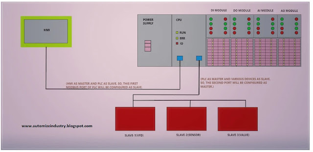
It
is also necessary to understand the topology used for Modbus RTU structure.
Refer the below image which must be used by programmers for establishing proper
communication.
Understanding Modbus Communication:
Many
programmers face issue in establishing Modbus connectivity in PLC. Before
proceeding for individual range of PLC’s, let’s have a look at the common steps
which must be undertaken in troubleshooting any Modbus port of Schneider range
of PLC’s.
·
The basic step a programmer
should check is to first verify the specifications of the Modbus device that he
is checking. It can be like; what is the physical interface that the device
uses and what are the parameters like parity, baud-rate, character format and
slave ID (in case the device is Modbus RTU). For Modbus TCPIP, only IP address
and slave ID of the device is required. The settings in PLC program must be
same as the device (apart from ID; otherwise communication will not happen. Keep
the document/technical catalogue of the device and PLC module ready for
testing. You must know what the registers available in the device for
communication are and how to address them properly.
·
Cable configuration and proper wiring is
must. Refer the below image which is used in standard practice:
Always refer the device and PLC catalogues
for their pin numbers. The connectors can be RJ45 type or DB9 type. Mostly,
communication can run even without a ground connection. But, it is recommended
to use it every time to avoid noise fluctuations. The voltage between neutral
and ground in the electrical panel should be in permissible limits (mostly less
than 2V). If you are facing more fluctuations, it is recommended to connect the
shield threads of the wire to a shielding point in the panel. Also, ensure that
there shouldn’t be any continuity between any of the pins as shown in figure.
· It is necessary to properly understand notations used for Modbus registers first of all. The address range applies to each type of register, and one need to look at the function code in the Modbus message packet to determine what register type is being referenced. The Modicon convention uses the first digit of a register reference to identify the register type. Register types and reference ranges recognized with Modicon notation are as follows:
0x = Coil = 00001-09999
1x = Discrete Input = 10001-19999
3x = Input Register = 30001-39999
4x = Holding Register = 40001-49999
On occasion, it is necessary to access more than 10,000 of a register type. Based on the original convention, there is another de facto standard that looks very similar. Additional register types and reference ranges recognized with Modicon notation are as follows:
0x = Coil = 000001-065535
1x = Discrete Input = 100001-165535
3x = Input Register = 300001-365535
4x = Holding Register = 400001-465535
When
using the extended register referencing, it is mandatory that all register
references be exactly six digits. Then only, the
difference can be identified between holding register 40001 and coil 40001. If coil 40001 is the target, it must
appear as 040001.
·
Extending it further, I would also like to
share one more point. Modbus protocol defines a register as 16-bit; however
there is a large scale demand in use for reading and writing data in more than
16 bits. The most common are IEEE 754 floating point and 32-bit integer. This
theory is also extended to double precision floating point and 64-bit integer. The
wide data simply consists of two consecutive "registers" treated as a
single wide register. Floating point in 32-bit IEEE 754 standard, and 32-bit
integer data, are widely used. Although the convention of register pairs is
widely recognized, agreement on whether the high order or low order register
should come first is not standardized. So, a wide number of softwares support a swap option. This means you simply
check the "swapped" option
if the other device treats wide data in the opposite order relative to the
software’s default order. In some cases, the “swap” option is more explicitly identified
as “high order data is in first register” or something to that effect.
·
Coming to the most important point, a
programmer must keep with him a USB-to RS485 converter; to test the Modbus
device or PLC. Also, there are various Modbus testing tools (softwares) in the
market. The most widely used is Modscan.
The programmer must have any of these softwares installed in his laptop. Corresponding
cable for the converter must also be kept ready. One must first check the master;
he must proceed to check slaves further.
·
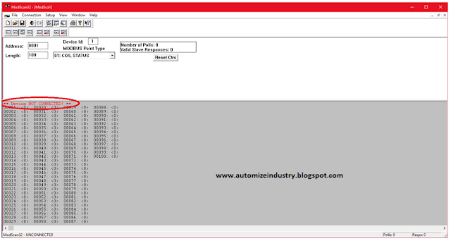
Refer the below images of Modscan software. The first one is for
Modbus RTU. Direct Connection to COM9 means
the communication port number of your laptop. You can find that in Device Manager – Ports section in your laptop. The configuration parameters must
match with that of the equipment you are testing. The second image is for
Modbus TCPIP. Enter the IP address of the device you are testing. The standard port for Modbus TCP is 502,
but port number can often be reassigned if desired.
Now, refer the below image after connection has been established. Address tab refers to the starting address of the register. Length tab refers to the number of registers that you want to view. Device ID tab refers to the unit ID of the device. Modbus Point Type refers to the function code that you want to work on. (For other function codes, you can use other softwares like ModbusPoll) As shown with red mark, if the device is properly connected with your PC, then it will show as Device Ok. When the device is connected, corresponding values will show in the registers. For coil status, only 0 or 1 will show in individual registers. (For example, 00001 can be 0 and 00002 can be 0 and 00003 can be 1)
If you want to deal with function codes 5,6,15 or 16; then I will explain you that too. For more simplicity, I will explain with the help of the given table below. Let us consider a fixed slave address with device ID as 5.
|
Function Code |
A Request Code |
Description |
|
1 |
05 01 0000 000B 0E84 |
This command is requesting on/off status
of discrete coils # 1 to 10 from the device. 05 – Slave ID (5 hex=address 5) 01 – Function Code 0000 – The data address of the first
coil to read (0 hex=0, +1 offset=coil#1) 000B – The total number of coils
requested (B hex=11, inputs 1 to 11) 0E84 – The CRC code |
|
2 |
05 02 0000 000B BAA9 |
This command is requesting on/off status
of discrete inputs # 1 to 10 from the device. 05 – Slave ID (5 hex=address 5) 02 – Function Code 0000 – The data address of the first
coil to read (0 hex=0, +1 offset=coil#1) 000B – The total number of coils
requested (B hex=11, inputs 1 to 11) BAA9 – The CRC code |
|
3 |
05 03 0000 000B 7687 |
This command is requesting data of
holding registers # 1 to 10 from the device. 05 – Slave ID (5 hex=address 5) 03 – Function Code 0000 – The data address of the first
register to read (0 hex=0, +1 offset=register#1) 000B – The total number of registers
requested (B hex=11, inputs 1 to 11) 7687 – The CRC code |
|
4 |
05 04 0000 000B B298 |
This command is requesting data of input
registers # 1 to 10 from the device. 05 – Slave ID (5 hex=address 5) 04 – Function Code 0000 – The data address of the first
register to read (0 hex=0, +1 offset=register#1) 000B – The total number of registers
requested (B hex=11, inputs 1 to 11) B298 – The CRC code |
|
5 |
05 05 0000 FF00 4E8B |
This command is writing a discrete coil
# 1 in the device. 05 – Slave ID (5 hex=address 5) 05 – Function Code 0000 – The data address of the coil to
write (0 hex=0, +1 offset=coil#1) FF00 – The status to write (FF00 hex=On,
0000 hex=Off) 4E8B – The CRC code |
|
6 |
05 06 0000 003C 9A9B |
This command is writing a single
register # 1 in the device. 05 – Slave ID (5 hex=address 5) 06 – Function Code 0000 – The data address of the register
to write (0 hex=0, +1 offset=register#1) 003C – The data to write (003C hex=60) 9A9B – The CRC code |
|
15 |
05 0F 0000 000A 02 CD01 BF0B |
This command is writing 10 coils # 1 to 9
in the device. 05 – Slave ID (5 hex=address 5) 0F – Function Code (0F hex=15) 0000 – The data address of the first coil
to write (0 hex=0, +1 offset=coil#1) 000A – The number of coils to write (0A
hex=10) 02 – The number of bytes to follow (10
coils means 2 bytes) CD01 – Coils #1 to 7(1100 1101=CD hex)
and coils #8 to 9(0000 0001=01 hex) BF0B – The CRC code |
|
16 |
05 10 0000 0003 06 0002 0004 0005 C6F0 |
This command is writing 3 registers # 1
to 3 in the device. 05 – Slave ID (5 hex=address 5) 10 – Function Code (10 hex=16) 0000 – The data address of the first
register to write (0 hex=0, +1 offset=register#1) 0003 – The number of registers to write
(03 hex=3) 06 – The number of bytes to follow (3 registers
of 16-bit each means 6 bytes) 0002 – Data to write in first register
(2=0002 hex) 0004 – Data to write in second register
(4=0004 hex) 0005 – Data to write in third register
(5=0005 hex) C6F0– The CRC code |
One more thing;
in our programming world, the most common techniques we cover are rebooting
(power recycle) of the device or laptop in worst scenario. I have covered the
general principles which normally are followed to troubleshoot modbus
connectivity issue. I have also not attempted to
cover every type of device. Each manufacturer has unique ways of handling
problems, and there are many other sorts of solutions that I have not included
here.
Thank you guys; we will cover the Modbus code troubleshooting for various
PLC’s used in Schneider in second part. If
you have any views or know some more methods, then I would be happy to get a
comment from you.


Thanks for shearing this kind of information modbus
ReplyDeleteThanks for shearing this kind of information modbus
ReplyDeleteThanks for shearing this kind of information modbus
ReplyDeleteI like your all post. You have done really good work. Thank you for the information you provide, it helped me a lot. crackroom.org I hope to have many more entries or so from you.
ReplyDeleteVery interesting blog.
Modbus Poll Crack
I like your all post. You have done really good work. Thank you for the information you provide, it helped me a lot. gurucrack.org I hope to have many more entries or so from you.
ReplyDeleteVery interesting blog.
Modbus Poll Crack
I thought this was a pretty interesting read when it comes to this topic. Thank you
ReplyDeleteModbus Poll Crack
SAM Broadcaster Pro Crack
Tally ERP Crack
Letasoft Sound Booster Crack
Dr Fone Crack
WindowManager Crack
Writing on trends is hard, but your blogs are doing this greatly. Winter Sale Jackets
ReplyDelete