General Theory of Encoders
25 Oct, 2020.
In this post, we will understand the encoders used in
industrial automation. This post is divided in two parts. Our first part will
cover the general theory of encoders and it’s various types. In the next part,
we will understand the general theory of an incremental encoder wiring outputs
and it’s resolution.
Hello engineers. We all are well-versed with a transducer. A transducer is
nothing but a device which converts a physical signal into an electrical
signal. In simpler terms, a normal sensor that you use in an application is
nothing but a transducer. Say for example, a flow transmitter. It senses the
flow of a liquid and correspondingly converts this physical type into
electrical analog signal (4-20 mA or 0-10 V). In this post, we will look into
one such device which converts mechanical motion into an electrical signal. It
is nothing but an encoder.
An encoder is a device which
converts motion into electrical signal. This electrical output can be digital
or analog. The output is then provided to some control device (like PLC) to
monitor the motion of the object and control the overall system accordingly. Encoders typically are used to measure one or more
specific parameters about the object, such as its speed, position, direction,
or to provide a count of the object or some related value. A simple
example can be considered of a sheet cutting machine. Imagine a cutting operation or machine that is designed to regularly
produce material of a certain fixed length. The raw material (metal sheet) is
fed continuously to the machine. The encoder is mounted on the sheet and you
have to cut 25 feet of the sheet continuously. The encoder will sense the
motion of the sheet and provide uninterrupted electrical pulses to the PLC.
When the PLC reads that 25 feet has been achieved by means of it’s internal
logic calculations, it will stop the movement logic and command the cutting logic
to cut that section and start the movement logic again. This way, the cycle
repeats in loop.
There are two
types of encoders used – linear and rotary.
Rotary Encoder Working Principle:
Let us first
consider a rotary encoder. This
encoder is used to sense the angular motion of an object. Various
technologies are used in rotary encoders to convert the motion input to an
electrical signal. The most commonly ones used are – optical, magnetic and
capacitive.
Optical Encoders :
This is one of the most used and accurate means of encoding. It mainly consists of a light source, a rotating disk that is patterned with a series of opaque lines and alternating translucent slots, and a photo detector. As the light passes through the rotating disk, a photo sensor mounted on the opposite side of the disk detects the light and generates a sinusoidal electrical signal (high and low) that corresponds to the presence of light detected from the translucent slots and the absence of light from the opaque lines. An electrical circuit then converts the sinusoidal signal to a square wave signal, which is a series of high and low pulses. These pulses are sent to a control circuit that can be used to measure the pulse count as the encoder rotates and use that data to determine a position for the rotating shaft or to control some action based on movement or position.
Magnetic Encoders :
Unlike an optical encoder which uses light as a means to encode, this type uses magnetic flux as the means. Magnetic encoders employ a signal detection system based on the variation of the magnetic flux generated by a magnet (one or more pole pairs) placed in rotation in front of a sensor, usually fixed to the encoder’s shaft. The variation of the magnetic field is sampled by the sensor and converted into an electric pulse, which determines the position. It is then converted into a square pulse by a control circuit.
Capacitive Encoders :
A capacitive encoder is a specific type of encoder which implements technology similar to that used in digital callipers to identify changes in capacitance using a high-frequency signal to measure rotary motion. Capacitive encoders are comprised of three major components: a stationary transmitter, a rotor stamped with a sinusoidal pattern, and a stationary receiver. As the rotor rotates, the pattern etched into it modulates the high-frequency electrical signal emitted by the transmitter at predetermined intervals. The receiver then reads the modulations and converts and outputs the modulated signal into increments of rotary motion.
Refer the below image for more understanding.
Linear Encoder Working Principle:
Now, let’s move
on into linear encoders. As the name
implies, it is used to sense the linear movement of an object. Refer the below
image. The main parts are the scale (with reference points) and signaling
method. The scale has special marks on its surface that help the sensing system
to determine its current position. Such labels are offset from each other by a
certain distance. The more a number of such marks and the denser they are
placed, the higher the resolution. The scale is generally glass and is cemented
to a support, usually an aluminum extrusion. The encoder assembly moves along
the entire scale length like a train on the tracks. Mostly, two types of
signaling methods are used for encoding – optical and magnetic. As we had
discussed earlier in the rotary encoder section, the working principle is the
same here too.
Now, both these types of encoders are further categorized
into two types – incremental and absolute.
Incremental Encoders :
These are the basic and simplest types of encoders used.
You can consider it as a simple counter. For example, in the optical encoder as
discussed, each slot counted denotes a pulse. So, it simply relies on pulse
counting and the PLC uses it compute it’s current position. Because they rely on pulse counting, there is no
unique digital signature that can be used to determine an absolute
position. So, in the event of power loss, the values of counts become zero.
Due to this, you cannot recognize the last held position of the device.
Absolute Encoders :
The above drawback of an incremental
encoder is covered by an absolute encoder. Here, you can know the exact
position of the device after power loss. In these encoders, unique digital
signature patterns are used for identifying the last held position.
So, what is that exact thing which distinguishes both these encoders? The answer is; unique digital signature patterns. Refer the below image for clarity.
As seen from the above image, incremental encoder has a slot position. That means, the signal can either be a 0 or 1; as discussed earlier. But, absolute encoder has a unique stamping pattern of opaque and transparent layers. There are many layers in this encoder. Each has a predefined slot positions for sensing. For example, if you refer the below image, all the layers starting from 1 to 5 (1 is the most above one and 5 is the most below one) have different bit positions. If I am moving the encoder, I will first encounter the value of 10000 and then 01000 and so on. The output is converted into a word and given to PLC. This was just an example. In reality, you will get proper counts like 1, 2,3,4,5 and so on in a linear sequence.
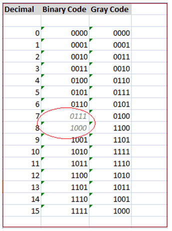
For your information, gray code is used instead of natural binary code. Gray code is used because only one bit value changes as the shaft moves from one position to the next. This eliminates problems of ambiguous outputs if there were multiple bits changing simultaneously. See the table below for reference. For numbers 7 and 8, the number of bits changed directly from 3 to 1. But, in gray code, bit positions change by only one. Unfortunately, PLCs typically use natural binary, not gray code. Therefore, the gray code generated by the encoder must be converted. Encoders optionally include a conversion circuit based on a micro controller that can convert the gray code to any other useful code, such as natural binary.
So, due
to this design, absolute encoders will give you the exact last position where
it was stopped; with the help of unique word values.
Encoders
are also differentiated by PPR (pulses per revolution). It’s simple, the number
of pulses it provides in one single revolution. Higher the PPR, higher will be
the resolution. Typical ones being used are 250, 500, 1000 and so on.
Choosing
the right type of encoder requires a proper knowledge of the application. It
can be like – which type of motion is to be considered (linear or rotary), what
parameters are being measured, is direction required, what are the
environmental conditions, what to do in case of power loss, resolution needed,
what are the electrical and mechanical requirements before choosing an encoder.
This lesson has been a basic introduction to the general
theory of encoders. The ways the encoders are built differ between
manufacturers and models, so I have just covered general principles without
enough detail to implement them in any given system. I have also not attempted
to cover every type of encoder. Each manufacturer has unique ways of handling
measurements, and there are many other sorts of encoders that we have not
included here.
Thank you guys; in the next topic, we will cover incremental encoder wiring outputs and it’s resolution methods. If you have any views or know some more methods, then I would be happy to get a comment from you.


Comments
Post a Comment
If you have any queries, please let me know